Supercharge Your Innovation With Domain-Expert AI Agents!

Hot nozzle structure of hot runner mold

A hot runner and mold technology, which is applied in the field of hot nozzle structure of hot runner molds, can solve the problems of broken nozzle, mold damage, unqualified injection products, etc., and achieve the effect of preventing the displacement of the nozzle

Pending Publication Date: 2019-04-26
BERPU MEDICAL TECH CO LTD
View PDF0 Cites 0 Cited by
  • Summary
  • Abstract
  • Description
  • Claims
  • Application Information

AI Technical Summary

Problems solved by technology

[0002] At present, the hot runner mold will thermally expand due to the mold temperature during the production process, especially the hot nozzle body will be along the figure 1 The thermal deformation in the thermal deformation direction A will generate shear force on the nozzle, resulting in the fracture of the nozzle and the deviation of the feed port, resulting in damage to the mold and unqualified injection molding products.

Method used


Image

  • Hot nozzle structure of hot runner mold
  • Hot nozzle structure of hot runner mold
  • Hot nozzle structure of hot runner mold

Examples


Embodiment Construction

[0028] The specific embodiments of the present invention will be described in detail below in conjunction with the accompanying drawings, so that those skilled in the art can more clearly understand how to practice the present invention. While the invention has been described in connection with preferred specific embodiments thereof, these embodiments are illustrative only and are not intended to limit the scope of the invention.

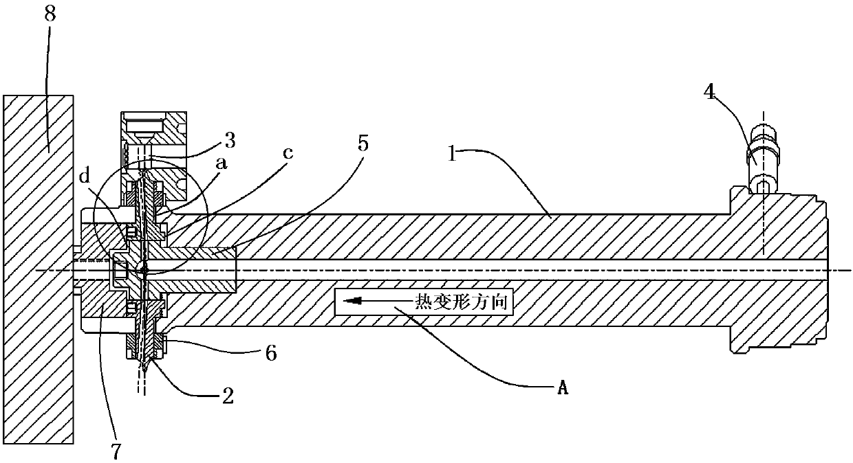
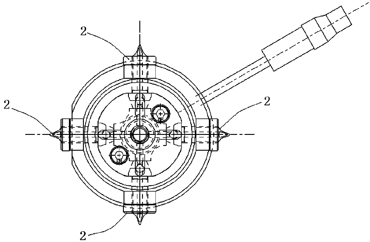
[0029] see figure 1 and figure 2 , a hot nozzle structure of a hot runner mold, including a hot nozzle body 1 and a nozzle 2 .

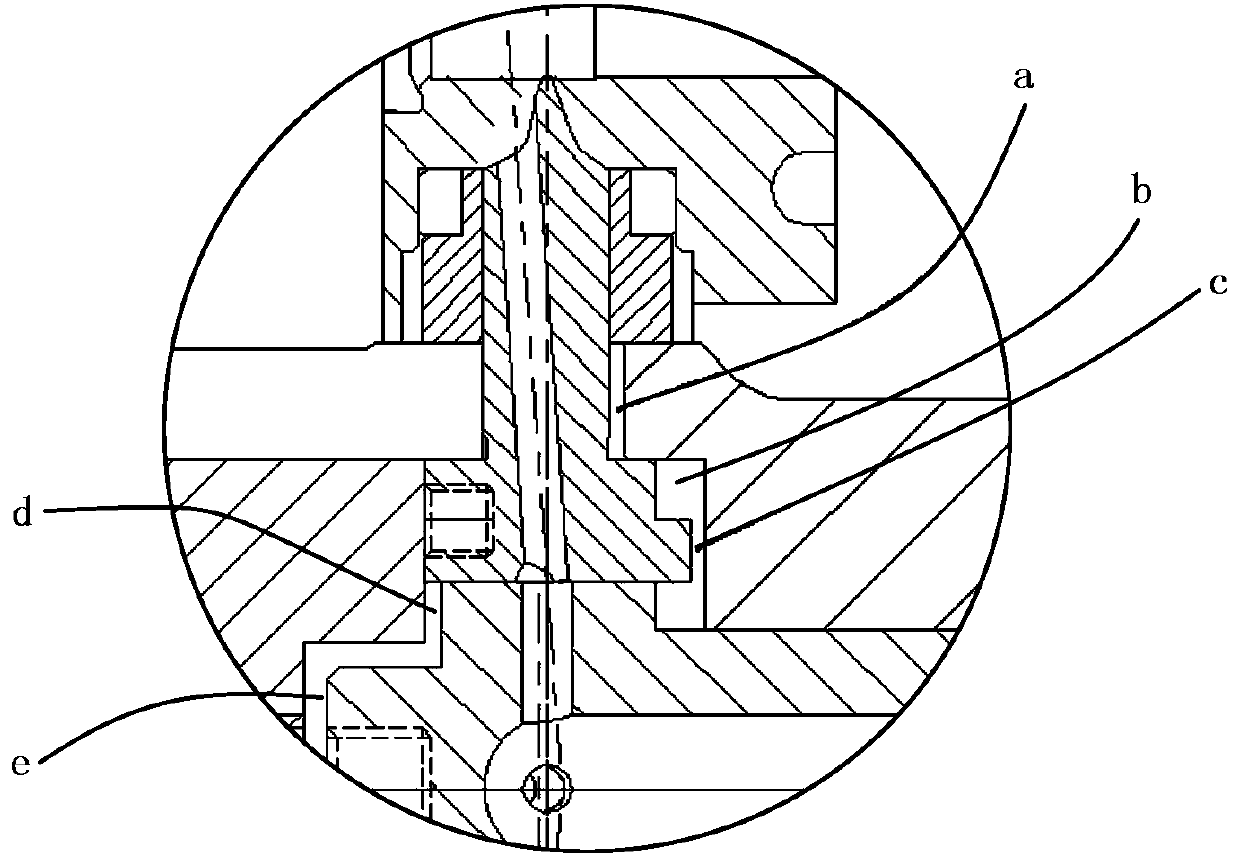
[0030] The hot nozzle body 1 is in the shape of a cylinder. The hot nozzle body 1 is arranged perpendicular to the cavity plate 3 of the hot runner mould. The head end of the hot nozzle body 1 is provided with a heater 4 . Through the main channel at both ends, a material transition sleeve 5 and four material nozzles 2 are provided at the tail end of the hot nozzle body 1 .

[0031] The material transition sleeve 5 is ...


PUM


Abstract

The invention provides a hot nozzle structure of a hot runner mold. The hot nozzle structure comprises a hot nozzle body and material nozzles. The hot nozzle body is columnar and perpendicular to a cavity plate of the hot runner mold, the one or more material nozzles are arranged at the tail end of the hot nozzle body, the material nozzles are fixed into the cavity plate, the material nozzles arearranged in the radial direction of the hot nozzle body, and axial gaps are formed in the joints of the tail end of the hot nozzle body and the side faces of the material nozzles. The material nozzlesare fixed into the cavity plate, so that displacement of the material nozzles is not generated; and the axial gaps are formed in the joints of the tail end of the hot nozzle and the side faces of thematerial nozzles, when the hot nozzle body expands due to thermal deformation, the hot nozzle body can axially slide through the axial gaps to offset the displacement, and the situation that the displacement of the material nozzles is generated, and then the mold and injection products are affected is avoided.

Description

technical field [0001] The invention relates to the technical field of hot runner molds, in particular to a hot nozzle structure of a hot runner mold. Background technique [0002] At present, the hot runner mold will thermally expand due to the mold temperature during the production process, especially the hot nozzle body will be along the figure 1 Thermal deformation in the thermal deformation direction A will generate shear force on the nozzle, causing the nozzle to break and the feed port to shift, resulting in damage to the mold and unqualified injection molding products. Contents of the invention [0003] Aiming at the above problems, the present invention provides a hot nozzle structure of a hot runner mold. [0004] The purpose of the present invention can be achieved through the following technical solutions: a hot nozzle structure of a hot runner mold, including a hot nozzle body and a nozzle, the hot nozzle body is cylindrical and perpendicular to the cavity pl...

Claims


Application Information

Patent Timeline
IPC IPC(8): B29C45/27
CPCB29C45/27
Inventor 张洪杰王兴国
Owner BERPU MEDICAL TECH CO LTD
Features
  • R&D
  • Intellectual Property
  • Life Sciences
  • Materials
  • Tech Scout
  • Unparalleled Data Quality
  • Higher Quality Content
  • 60% Fewer Hallucinations
Learn More