A Classified Pressure Relief Mechanism for Electric High Voltage Switchgear

A high-voltage switchgear and pressure relief technology, which is applied in the direction of switchgear, switchgear settings, electrical components, etc., can solve the problems that faulty gas cannot be eliminated in time, safety performance cannot be fully reflected, and the pressure of faulty gas is backlogged, etc., so as to save maintenance Replacement time, avoid one-time use replacement, and improve the effect of safety performance

Active Publication Date: 2020-09-01
国网山东省电力公司沂源县供电公司
View PDF7 Cites 0 Cited by
  • Summary
  • Abstract
  • Description
  • Claims
  • Application Information

AI Technical Summary

Problems solved by technology

[0004] However, it is also due to the fact that the bending of the metal roof completely opens the high pressure of the faulty high-temperature gas. When the pressure of the faulty gas does not reach the shear force required to cut the nylon bolts, the faulty gas cannot be removed in time, which may easily cause the pressure of the faulty gas. Backlog, and it is easy to cause the threat of impact damage to the staff who are about to open the closed cabinet door for maintenance, and the safety performance cannot be fully reflected. Therefore, a graded pressure relief mechanism for electric high-voltage switchgear is proposed to solve the above problems

Method used


Image

  • A Classified Pressure Relief Mechanism for Electric High Voltage Switchgear
  • A Classified Pressure Relief Mechanism for Electric High Voltage Switchgear
  • A Classified Pressure Relief Mechanism for Electric High Voltage Switchgear

Examples


Embodiment 1

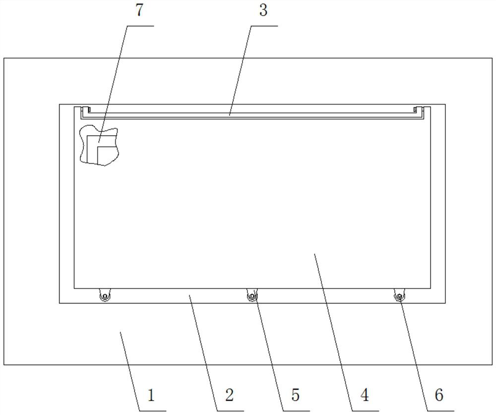
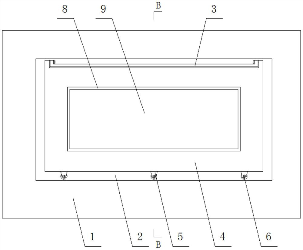
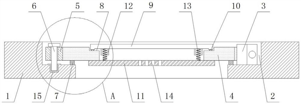
[0024] see Figure 2-4 , a graded pressure relief mechanism for electric high-voltage switchgear, including a cabinet top cover 1, a pressure relief channel 2, a hinge support 3, a top plate 4, a mounting buckle 5, nylon bolts 6 and a sealing ring I7, and the front of the cabinet top cover 1 There is a pressure relief channel 2 in the middle, and a hinge support 3 is fixedly installed on the inner bottom of one side of the pressure relief channel 2. The side of the cabinet is fixedly connected with the installation buckle 5, the installation buckle 5 is fixedly connected with the cabinet top cover 1 through the nylon bolt 6, the nylon bolt 6 is threaded with the cabinet top cover 1, the edge of the bottom of the top plate 4 is fixedly installed with a sealing ring Ⅰ7, and the top plate 4 passes through The sealing ring I7 seals the pressure relief channel 2 opened on the top of the top cover 1 of the cabinet, and the front of the top plate 4 is provided with a secondary pressu...


PUM


Abstract

The invention discloses a power high-voltage switch cabinet graded pressure relief mechanism, which comprises a cabinet top cover, a pressure relief through groove, a hinge support, a top plate, mounting buckles, a nylon bolt and a sealing ring I. The pressure relief through groove is formed in the middle of the front face of the cabinet top cover, and the hinge support is fixedly mounted at the inner bottom of one edge of the pressure relief through groove. By additionally arranging a secondary pressure relief plate on the existing top plate and mounting the secondary pressure relief plate ona pressure bearing steel plate through a pressure relief tension spring, fault gas pressures can be divided into three grades, namely the impact gas pressure which can be borne by an operator, the impact gas pressure which cannot cut off the nylon bolt, and the impact gas pressure which can cut off the nylon bolt, correspondingly, pressure relief is carried out by opening a cabinet door by the operator, pressure relief is carried out in the modes that fault gas jacks the secondary pressure relief plate and passes through a gap opening between the secondary pressure relief plate and the top plate through a vent hole, and pressure relief is carried out by shearing the nylon bolt and completely opening the top plate, so that the different fault gas pressures can be relieved in a graded modeto improve safety performance of pressure relief of the fault gas of a power distribution cabinet.

Description

technical field [0001] The invention relates to power distribution equipment technology, in particular to a graded pressure relief mechanism for a high-voltage electric switchgear. Background technique [0002] Power high-voltage switchgear is an important part of high-voltage power distribution equipment. According to its internal functions, it mainly includes main busbar room, circuit breaker handcart room, cable room, instrument room, secondary terminal room, etc., of which the main busbar room, Both the handcart room and the cable room of the circuit breaker have a primary charged body. When a short-circuit fault occurs inside the circuit breaker, the primary charged body will generate an arc, and the internal pressure of the switch cabinet will rise. It is necessary to release the high temperature and high pressure gas generated by the fault to prevent high temperature. The high-pressure gas breaks through the partition, causing damage to the indoor components of the ad...

Claims


Application Information

Patent Timeline
Patent Type & Authority Patents(China)
IPC IPC(8): H02B1/30H02B13/025
CPCH02B1/30H02B13/025
Inventor 孙泽坤司继海刘延会贺志伟王潇何珍窦丰明张吉庆高鹏李明卞振华赵丁主军宋以新戴文利任纪菊周刚
Owner 国网山东省电力公司沂源县供电公司
Why Eureka
Try Eureka