
Portal steel frame shearing knife for steel structure construction

A technology of steel structure construction and shearing knife, which is applied in the field of steel structure, can solve the problems of poor shearing effect at joints, inconvenient movement of plates, and easy scratching of hands, so as to avoid being stuck, not easy to jam the knife, and avoid The effect of scratching hands

Active Publication Date: 2020-02-07
合肥巍华钢结构有限公司
View PDF11 Cites 0 Cited by
  • Summary
  • Abstract
  • Description
  • Claims
  • Application Information

AI Technical Summary

Problems solved by technology

[0008] In order to solve the above problems, the present invention provides a door-type steel frame shearing knife for steel structure construction, which can solve the inconvenience of plate movement when the door-type steel frame is sheared, the poor shearing effect at the joint after the plate is moved, and the It is easy to jam the knife when cutting and easy to scratch the hand after the plate is cut. It can realize the function of safe and efficient cutting of the plate. It has the advantages of convenient movement, not easy to jam the knife and safe operation.

Method used


Image

  • Portal steel frame shearing knife for steel structure construction
  • Portal steel frame shearing knife for steel structure construction
  • Portal steel frame shearing knife for steel structure construction

Examples


Embodiment Construction

[0027] In order to make the technical means, creative features, goals and effects achieved by the present invention easy to understand, the present invention will be further described below in conjunction with specific illustrations. It should be noted that, in the case of no conflict, the embodiments in the present application and the features in the embodiments can be combined with each other.

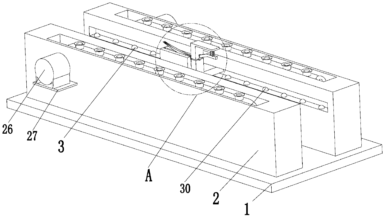
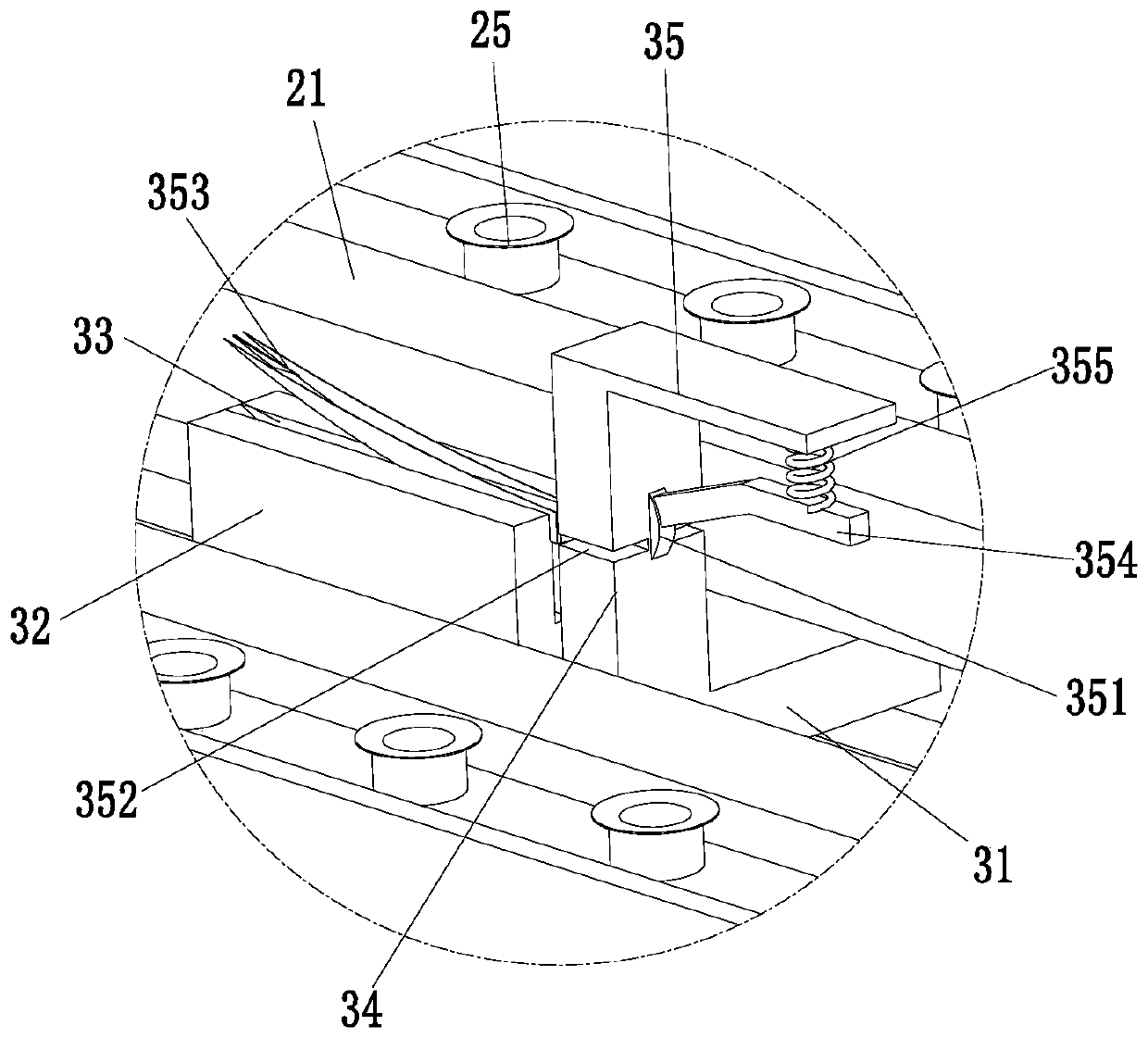
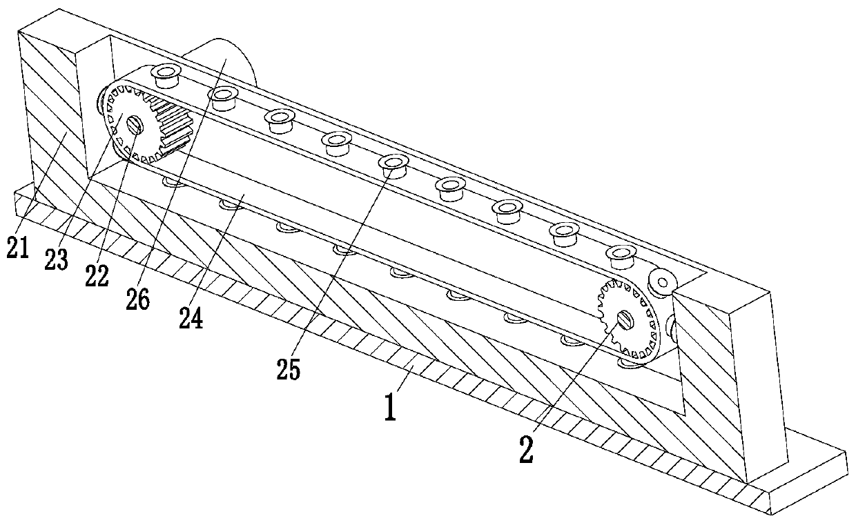
[0028] Such as Figure 1 to Figure 4 As shown, a door-type steel frame shearing knife for steel structure construction includes a base plate 1, a transmission mechanism 2 and a shearing mechanism 3. A shearing mechanism 3 is installed between the mechanisms 2 through a sliding fit.

[0029] The transmission mechanism 2 includes a transmission platform 21, the rear end of the upper end surface of the base plate 1 is equipped with a transmission platform 21, the upper end surface of the transmission platform 21 is provided with a groove, and a support rod 22 is installed symmetrically...


PUM


Abstract

The invention relates to a portal type steel frame shearing knife for steel structure construction. The portal type steel frame shearing knife comprises a bottom plate, transporting mechanisms and a shearing mechanism, wherein the transporting mechanisms are in front-and-rear symmetry arrangement on the front side and the rear side of the upper end surface of the bottom plate; the shearing mechanism is mounted between the front transporting mechanism and the rear transporting mechanism through a sliding cooperation manner; each transporting mechanism comprises a transporting platform; each transporting platform is mounted at the rear end of the upper end surface of the bottom plate; a groove is formed in the upper end surface of each transporting platform; supporting rods are mounted between the front inner side wall and the rear inner side wall of each groove in a bilateral symmetry manner; each rotating fluted disc is mounted at the middle part of the side wall of the corresponding supporting rod through a corresponding bearing; and each left rotating fluted disc is connected with the corresponding right rotating fluted disc through a corresponding conveyer belt. Through the adoption of the portal type steel frame shearing knife disclosed by the invention, the problems that during shearing of a portal type steel frame, a panel is inconvenient to move, after the panel is moved, the shearing effect at a joint is poor, during shearing, the knife is easy to clamp, and the sheared panel is freely placed, so that hands are easy to scratch can be solved, and the function of safeand high-efficiency shearing of the panel can be realized; and the portal type steel frame shearing knife has the advantages of being convenient to move, and safe to operate, and the knife is not liable to clamp.

Description

technical field [0001] The invention relates to the field of steel structures, in particular to a door-type steel frame shearing knife for steel structure construction. Background technique [0002] Steel structure is a structure composed of steel materials, which is one of the main types of building structures. The components or parts of the steel structure are usually connected by welds, bolts or rivets, because of its light weight and easy construction, it is widely used. It is used in large factories, stadiums, super high-rises and other fields. [0003] During the construction of the steel structure, due to the inconsistency of the plates of each component, the operation methods are also different. In the construction of the steel structure, the plates used in the portal steel frame are very thin, and the shearing method should be used to avoid using flames when cutting the plates. Cutting, this is because the edge of the plate will be greatly deformed by flame cutting...

Claims


Application Information

Patent Timeline
Patent Type & Authority Patents(China)
IPC IPC(8): B23D15/08B23D15/12B23D33/02
CPCB23D15/08B23D15/12B23D33/02
Inventor 韦俊田
Owner 合肥巍华钢结构有限公司
Learn More