Automatic drawer cabinet

A drawer cabinet, automatic technology, applied in the field of lockers, can solve the problems of increasing storage costs, messy workshop arrangement, etc.

Pending Publication Date: 2019-04-30
扬中凯悦铜材有限公司
View PDF2 Cites 0 Cited by
  • Summary
  • Abstract
  • Description
  • Claims
  • Application Information

AI Technical Summary

Problems solved by technology

[0002] Copper bars play the role of transmitting current and connecting electrical equipment in the circuit. Different power distribution equipment has different specifications for copper bars, and there are many types. As a manufacturer, a large ground position is required to place copper bars of different specifications. Leading to messy placement in the workshop and increased storage costs

Method used


Image

  • Automatic drawer cabinet
  • Automatic drawer cabinet
  • Automatic drawer cabinet

Examples


Embodiment Construction

[0020] The present invention will be described in further detail below in conjunction with the accompanying drawings and embodiments.

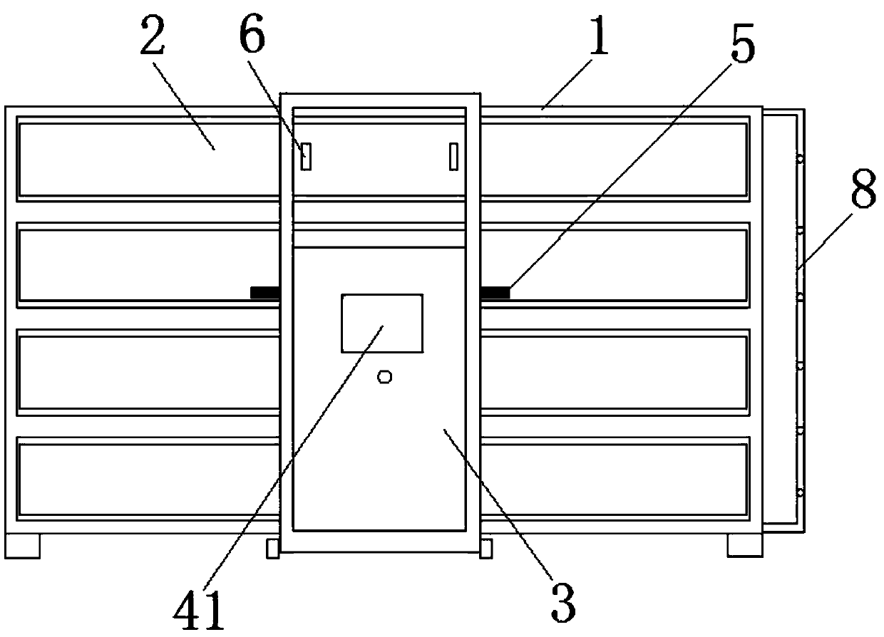
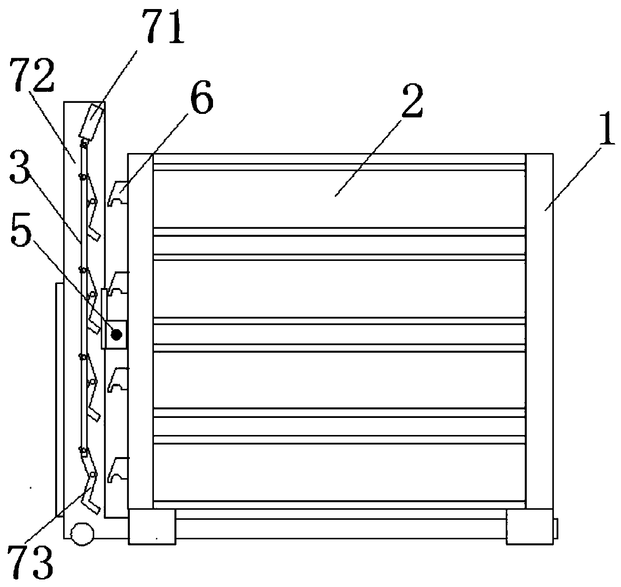
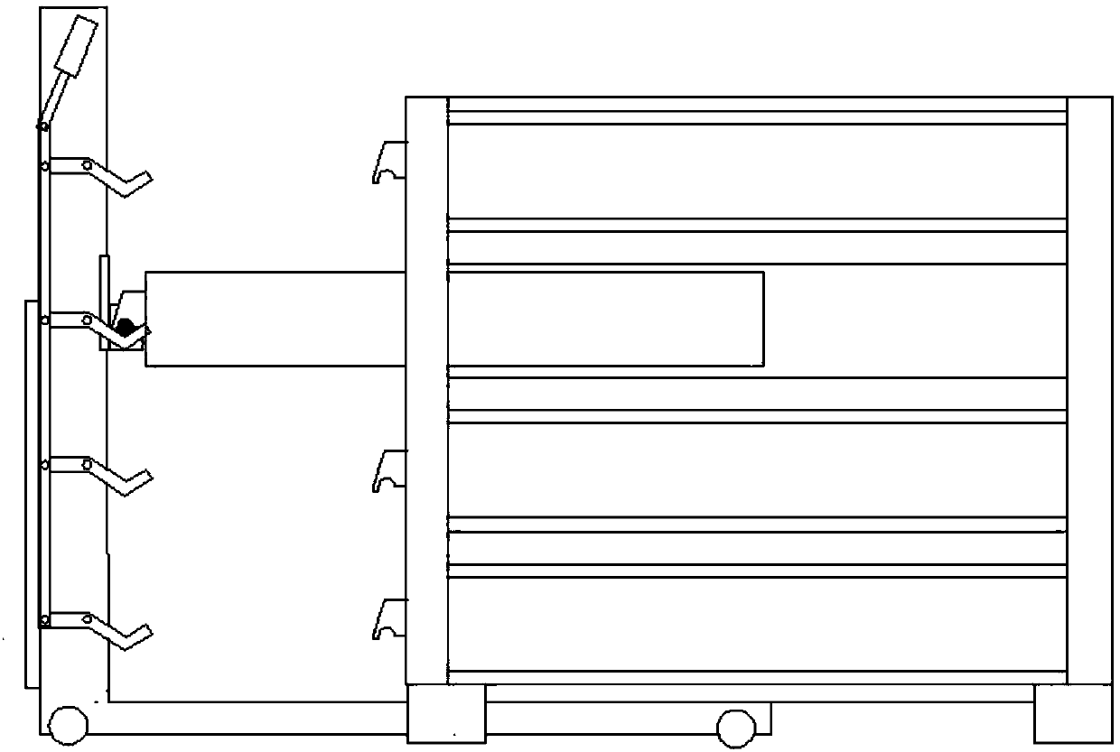
[0021] Such as Figure 1-3 As shown, the automatic drawer cabinet includes a cabinet body 1, a drawer unit 2, a mobile trolley 3 and a PLC controller. The mobile trolley 3 pulls out the drawer unit 2 from the cabinet body 1 and resets it; the PLC controller is used to control the mobile trolley 3 actions.

[0022] Specifically, a pull-out rod 5 is set on the side of the mobile trolley 3 facing the cabinet 1, and the position height of the pull-out rod 5 can be adjusted up and down by hydraulic cylinder control; correspondingly, a pull-out rod clip 6 is set on the panel of the drawer unit 2, It cooperates with the extraction rod 5 and engages with it.

[0023] It also includes an auxiliary support assembly, which is arranged on both sides of the mobile trolley 3 and is used to support the extraction rod 5; the auxiliary support assembly inclu...


PUM


Abstract

The invention relates to an automatic drawer cabinet. The drawer cabinet includes a cabinet body, drawer units, a moving dolly and a PLC; the moving dolly draws out and resets the drawer units from the cabinet body; and the PLC is used for controlling the motion of the moving dolly. The drawer cabinet can effectively utilize the three-dimensional space of a workshop, so that structured and orderedpurposes can be achieved.

Description

technical field [0001] The invention relates to a storage cabinet, and specifically discloses an automatic drawer cabinet. Background technique [0002] Copper bars play the role of transmitting current and connecting electrical equipment in the circuit. Different power distribution equipment has different specifications for copper bars, and there are many types. As a manufacturer, a large ground position is required to place copper bars of different specifications. It leads to messy placement in the workshop and increases storage costs. Contents of the invention [0003] The object of the present invention is to provide an automatic chest of drawers with simple structure, convenient operation and full use of the three-dimensional space of the workshop in order to solve the above problems. [0004] The technical scheme that the present invention adopts is such: [0005] The automatic drawer cabinet includes a cabinet body, a drawer unit, a mobile trolley and a PLC contro...

Claims


Application Information

Patent Timeline
Patent Type & Authority Applications(China)
IPC IPC(8): H02B11/127H02B11/02
CPCH02B11/02H02B11/127
Inventor 陈文
Owner 扬中凯悦铜材有限公司
Why Eureka
Try Eureka