Heat insulation pad with conduction and heat radiation effects

A technology of heat dissipation and heat insulation pads, which is applied in the field of kitchen utensils, and can solve problems such as easy wear, inconvenient movement and taking, and inconvenient cleaning.

Inactive Publication Date: 2019-05-03
WUJIANG GERUIFU HARDWARE
View PDF5 Cites 0 Cited by
  • Summary
  • Abstract
  • Description
  • Claims
  • Application Information

AI Technical Summary

Problems solved by technology

If the traditional heat insulation pad is simply made of plastic, it is easy to wear and tear after long-term use. The plastic heat insulation pad is easy to deform after supporting the high-temperature container for a long time, and the plastic is also easy to slip; the heat insulation pad made of multi-layer fabrics is stitched together. It is not easy to clean. After cleaning, because the multi-layer fabrics are stitched with a certain thickness, it needs to be dried for a long time before it can be used next time. At the same time, the fabric is easy to age after repeated use; heat insulation pads with metal structures are generally made into fixed The style of the support frame for thermal insulation
[0003] Heat insulation pads in the prior art are usually made into a flat plate, and this flat plate structure is not easy to be plasticized or deformed. Although it can achieve the effect of supporting heat insulation, in daily life, heat insulation pads with a flat plate structure, especially metal insulation The heat pad is placed on the table, which is inconvenient to move and take, and it cannot wrap the heat container that needs to be transported. At the same time, the surface-to-surface bonding between the bottom of the heat container and the heat insulation pad is not convenient for the heat insulation pad during the heat insulation process. heat conduction and heat dissipation, thus affecting the use of

Method used


Image

  • Heat insulation pad with conduction and heat radiation effects
  • Heat insulation pad with conduction and heat radiation effects
  • Heat insulation pad with conduction and heat radiation effects

Examples


Embodiment Construction

[0021] The present invention will now be further described in detail in conjunction with the accompanying drawings and embodiments. These drawings are all simplified schematic diagrams, only illustrating the basic structure of the present invention in a schematic manner, so it only shows the composition related to the present invention.

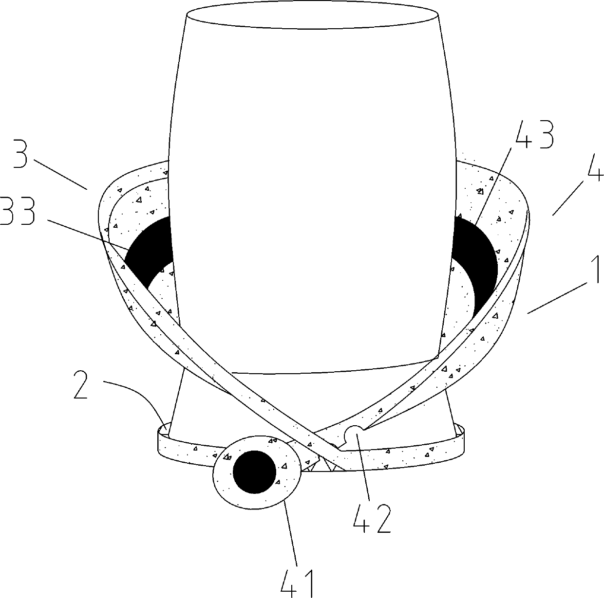
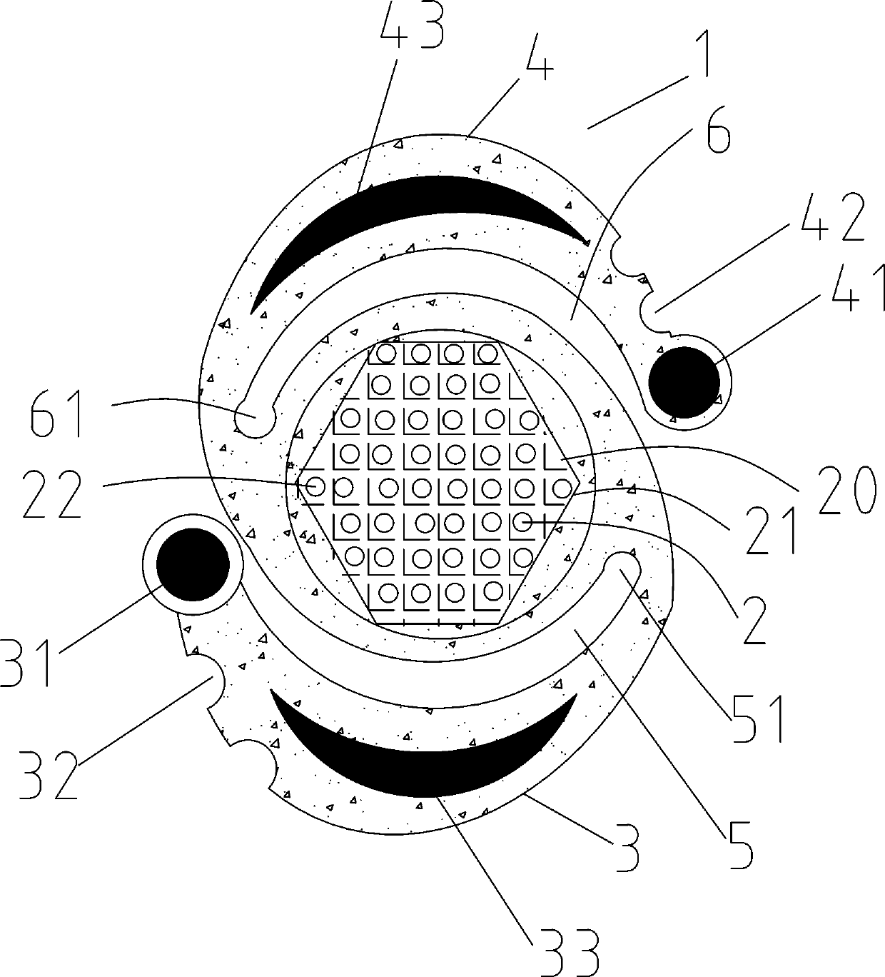
[0022] Such as Figure 1~2 As shown, it is a structural schematic diagram of a preferred embodiment of the present invention, specifically a heat insulation pad with conduction and heat dissipation, including a heat insulation bottom plate 2, and a defined cavity 20 is arranged in the middle of the heat insulation bottom plate 2, and the defined cavity 20 is fixedly arranged There is a heat-conducting support grid 21 matching the shape of the defined cavity 20, the heat-conducted support grid 21 is a metal grid frame, and an accommodation cavity is formed between the heat-conducting support grid 21 and the defined cavity 20, and a metal bump 2...


PUM


Abstract

The invention relates to a heat insulation pad with conduction and heat radiation effects. The heat insulation pad comprises a heat insulation bottom plate, wherein metal convex blocks and a heat conduction support grid plate of a metal net rack structure are arranged in a defining cavity of the heat insulation bottom plate; the outer edge of the heat insulation bottom plate is connected with thehead end of a first arc-shaped baffle plate; a first position limiting groove is formed in the inner side of a connecting part; a first spacing groove is formed between the first arc-shaped baffle plate and the heat insulation bottom plate; a first clamp connection ring is arranged at the tail end of the first arc-shaped baffle plate; first clamp connection grooves are formed in the outer edge ofthe first arc-shaped baffle plate; the outer edge of the heat insulation bottom plate is connected with the head end of a second arc-shaped baffle plate, and a second position limiting groove is formed in the inner side of the connecting part; a second spacing groove is formed between the second arc-shaped baffle plate and the heat insulation bottom plate; a second clamp connection ring is arranged at the tail end of the second arc-shaped baffle plate; and second clamp connection grooves are formed in the outer edge of the second arc-shaped baffle plate. The heat insulation pad provided by theinvention has the advantages that heat container can be carried in an auxiliary way; the flexible shaping support can be realized; meanwhile, the taking and the placing are convenient; and the effectof carrying the heat containers in the auxiliary way or defining and supporting the heat containers is achieved.

Description

technical field [0001] The present application relates to a kitchen utensil, in particular to a heat insulation pad with conduction and heat dissipation functions. Background technique [0002] There are many potholders on the market, including plastic potholders, potholders made from layers of stitched fabric, and metal potholders. If the traditional heat insulation pad is simply made of plastic, it is easy to wear and tear after long-term use. The plastic heat insulation pad is easy to deform after supporting the high-temperature container for a long time, and the plastic is also easy to slip; the heat insulation pad made of multi-layer fabrics is stitched together. It is not easy to clean. After cleaning, because the multi-layer fabrics are stitched with a certain thickness, it needs to be dried for a long time before it can be used next time. At the same time, the fabric is easy to age after repeated use; heat insulation pads with metal structures are generally made into...

Claims


Application Information

Patent Timeline
Patent Type & Authority Applications(China)
IPC IPC(8): A47G23/06
Inventor 刘鹭
Owner WUJIANG GERUIFU HARDWARE
Why Eureka
Try Eureka