
A supercharging device and supercharging mechanism thereof

A technology of hydraulic press and connecting rod mechanism, which is applied in forging/pressing/hammer device, driving device of forging press, forging press, etc. It can solve the problems of low processing efficiency, inability to have large mold opening space, small stroke, etc.

Active Publication Date: 2020-07-28
江苏宗颐新材料科技有限公司
View PDF12 Cites 0 Cited by
  • Summary
  • Abstract
  • Description
  • Claims
  • Application Information

AI Technical Summary

Problems solved by technology

[0005] The purpose of the present invention is to provide a supercharging mechanism to solve the problem that the supercharging mechanism in the prior art has a small stroke due to the constraint of the toggle link, and cannot have a large mold opening space and cannot be used for applications that require a large space. The problem of the situation; the object of the present invention is also to provide a kind of supercharging device with the supercharging mechanism, to solve the problem that the supercharging device in the prior art has a small stroke due to the constraints of the toggle linkage mechanism and cannot have a larger The problem of low processing efficiency due to mold opening space

Method used


Image

  • A supercharging device and supercharging mechanism thereof
  • A supercharging device and supercharging mechanism thereof
  • A supercharging device and supercharging mechanism thereof

Examples


Embodiment Construction

[0029] Embodiments of the present invention will be further described below in conjunction with the accompanying drawings.

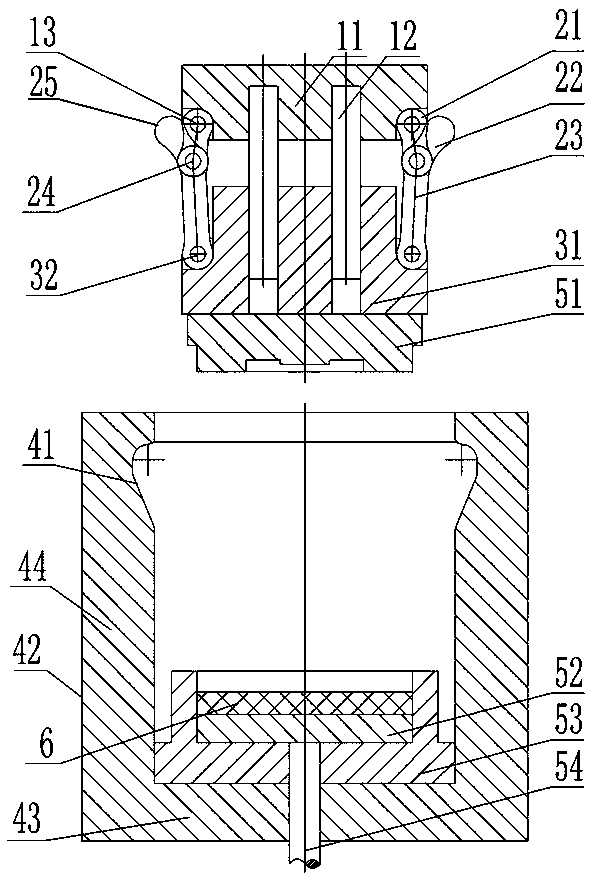
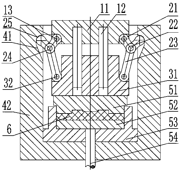
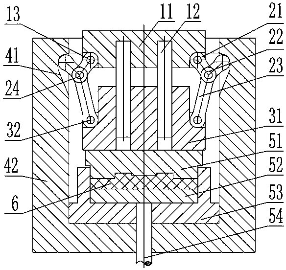
[0030] Embodiment 1 of the booster mechanism of the present invention, the booster mechanism is used in the liquid die forging process of large workpieces. like Figure 1 to Figure 6 As shown, the pressurizing mechanism includes a mold clamping and pressing mechanism installed on the movable beam of the hydraulic press and a constraint frame 42 installed on the workbench of the hydraulic press. The specific structure is as figure 1 , figure 2 , image 3 and Figure 4 As shown, the constraining frame 42 is a combined structure. The constraining frame 42 includes a bottom plate 43 and a side plate 44 fixedly connected to the bottom plate 43. The bottom plate 43 is used to install the lower die of the liquid forging die. perforated. The side plate 44 is rigidly connected to the bottom plate 43 , and a cross bar is connected above the side plate 44 to...


PUM


Abstract

The invention relates to a pressurizing device and a pressurizing mechanism thereof. The pressurizing mechanism comprises a restraining framework and a mold closing pressure-applying mechanism. The mold closing pressure-applying mechanism comprises a fixator and a connector. The fixator is connected with an upper mold. The connector is connected with a movable transverse beam of a hydraulic machine. Two or more sets of symmetrically-arranged elbow connecting rod mechanisms are arranged between the fixator and the connector. Each elbow connecting rod mechanism comprises a second elbow rod, a first elbow rod hinged to the fixator and a connecting rod hinged to the connector. The mold closing pressure-applying mechanism further comprises a swinging limiting structure by which it is guaranteedthat certain angle exists between each first elbow rod and the corresponding connecting rod, and the first elbow rod and the connecting rod are not pulled straight. Each elbow connecting rod mechanism further comprises an elbow rod limiting structure by which second elbow rods are kept to outward-inclined initial positions before mold closing is conducted. The second elbow rods have cooperating structures. Sliding holes are formed in the restraining framework. The second elbow rods can be brought out from the sliding holes. A pressure-applying structure can be separated from the restraining framework. The hydraulic machine has bigger molding opening space, and technological operation is convenient.

Description

technical field [0001] The invention relates to a supercharging device and a supercharging mechanism thereof. Background technique [0002] The liquid die forging process requires that after the metal melt is poured into the concave mold cavity, the upper mold and the concave mold are quickly closed and high mechanical pressure is applied to the liquid or semi-solid metal in the cavity to make it crystallize and solidify under pressure. And produce a certain plastic deformation, thereby eliminating casting defects and obtaining high-quality liquid forgings. The liquid die forging process generally makes the material crystallize, solidify, cool and form under the pressure of 30MPa ~ 120MPa. The hydraulic press is a common equipment for liquid die forging, which can meet the forming process requirements of general-sized parts, but for liquid forgings with large cross-sectional dimensions, it is A hydraulic press with a large tonnage needs to be used, and the equipment cost is...

Claims


Application Information

Patent Timeline
Patent Type & Authority Patents(China)
IPC IPC(8): B21J9/18B21J9/02B21J5/02
Inventor 虞跨海杨永顺杨茜陈曦杨正海
Owner 江苏宗颐新材料科技有限公司
Learn More