
Hydraulic machine for hub forming

A technology of hydraulic presses and hubs, which is applied in the field of hydraulic presses and can solve problems such as large space and small working strokes that cannot be used

Active Publication Date: 2019-05-14
江苏宗颐新材料科技有限公司
View PDF12 Cites 3 Cited by
  • Summary
  • Abstract
  • Description
  • Claims
  • Application Information

AI Technical Summary

Problems solved by technology

[0005] The object of the present invention is to provide a hydraulic press for wheel hub forming, to solve the problem that the forming equipment with toggle linkage mechanism in the prior art is affected by the toggle linkage and has a small working stroke, which cannot be used for large space situation problem

Method used


Image

  • Hydraulic machine for hub forming
  • Hydraulic machine for hub forming
  • Hydraulic machine for hub forming

Examples


Embodiment Construction

[0024] Embodiments of the present invention will be further described below in conjunction with the accompanying drawings.

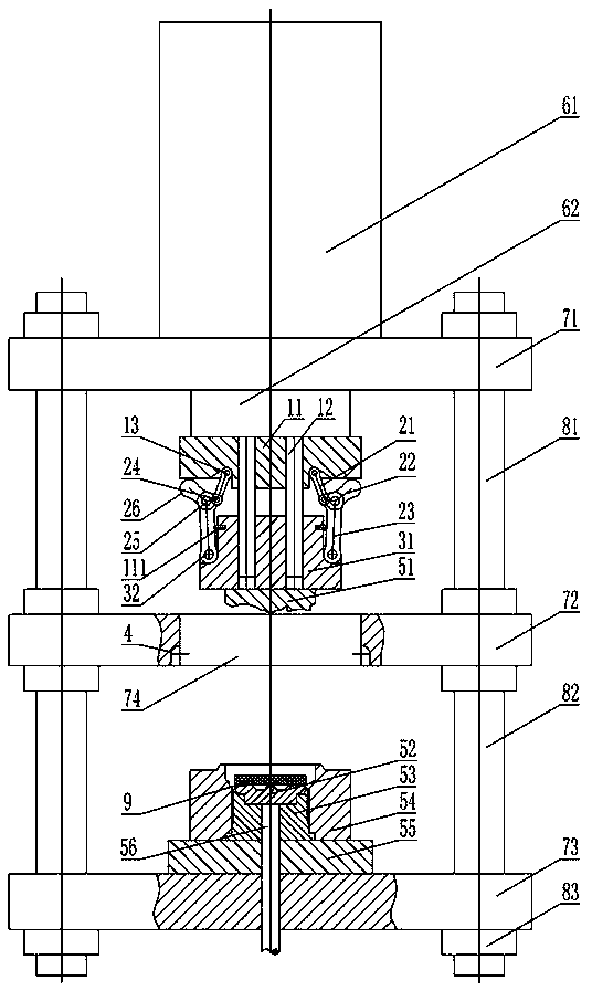
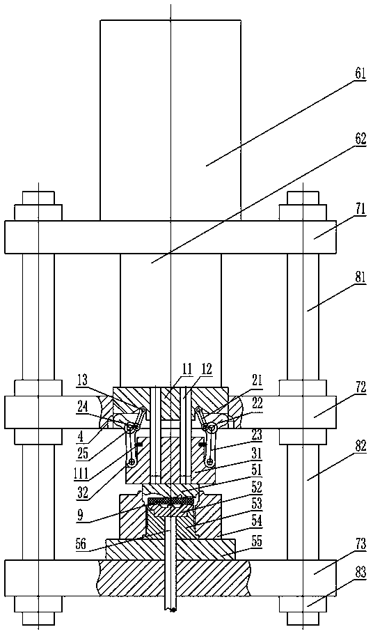
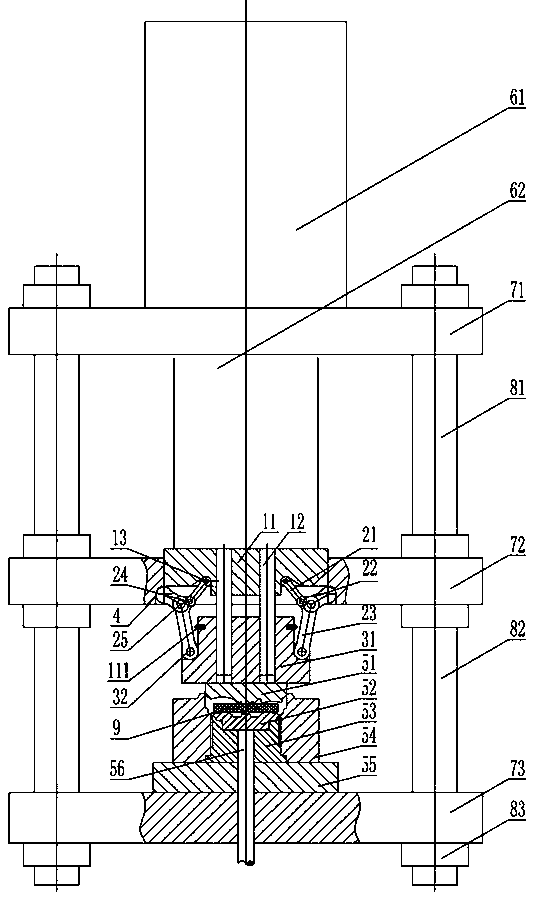
[0025] Embodiment 1 of the hydraulic press for wheel hub forming of the present invention, the hydraulic press is used in situations such as wheel hub extrusion forming that require a large operating space and a small force stroke. Such as Figure 1 to Figure 6 As shown, the hydraulic machine includes a frame, and the frame includes a vertically arranged column and an upper beam 71, a middle beam 72 and a lower beam 73 arranged at intervals along the axial direction of the column, and the column includes a frame connected between the upper beam 71 and the middle beam 72. The upper link 81 and the lower link 82 connecting the middle beam 72 and the lower beam 73, the upper beam 71 is fixedly equipped with a hydraulic cylinder 61, and the piston rod 62 of the hydraulic cylinder 61 extends downward. The following of the lower beam 73 is fixed with an eject...


PUM


Abstract

The invention relates to a hydraulic machine for hub forming. The hydraulic machine for hub forming comprises a rack and a die assembly pressing mechanism. The die assembly pressing mechanism comprises a fixator and a connector. At least two sets of symmetrically-arranged elbow connecting rod mechanisms are arranged between the fixator and the connector. Each elbow connecting rod mechanism comprises a second elbow rod, a first elbow rod hinged to the fixator, and a connecting rod hinged to the connector. The die assembly pressing mechanism further comprises a swing limiting structure for guaranteeing that certain angles are formed between the first elbow rods and the connecting rods, and the first elbow rods and the connecting rods cannot be straightened. The elbow connecting rod mechanisms further comprise elbow rod limiting structures for keeping the second elbow rods at outwards-inclined initial positions before die assembly. The second elbow rods are provided with cooperation mechanisms, sliding holes are formed in the portions, located on the outer sides of the second elbow rods, of the rack, and the second elbow rods are in abutting cooperation with the sliding holes after sliding into the sliding holes and swing around the abutting positions to jack the fixator to achieve die assembly pressurization. The die assembly pressing mechanism can be separated from the sliding holes, and the hydraulic machine has large die opening space.

Description

technical field [0001] The invention relates to a hydraulic press for forming a wheel hub. Background technique [0002] Light alloy automotive wheel hub parts need a lot of pressure when they are precision extruded, and at the same time need a large mold opening space when loading materials and taking out products. The working pressure of the hydraulic press is high, the working stroke can be freely controlled and the adjustment range is large, and it is widely used in the hub forming operation. However, the configuration of the hydraulic press with high pressure is relatively complicated. Generally, it needs to be equipped with an independent pump station, control part and hydraulic circuit. extremely high. [0003] The Chinese invention patent application document with the application publication number CN106182861A discloses a cylinder connecting rod drive system for a compound transmission hydraulic machine, which includes a symmetrical connecting rod booster mechanism...

Claims


Application Information

Patent Timeline
Patent Type & Authority Applications(China)
IPC IPC(8): B21C23/21B21C25/00B21C23/18
Inventor 杨茜杨永顺虞跨海杨正海
Owner 江苏宗颐新材料科技有限公司
Learn More