Bearing sealing structure and electric spindle with same

A bearing sealing and shaft core technology, applied in the direction of bearing components, shafts and bearings, engine sealing, etc., can solve the problems of leakage of the sealing structure, affecting the service life of the motorized spindle, reducing the bearing performance, etc., to achieve good sealing, enhanced waterproofing Dust, Enhanced Effect

Active Publication Date: 2019-05-03
GUANGZHOU HAOZHI ELECTROMECHANICAL
View PDF12 Cites 3 Cited by
  • Summary
  • Abstract
  • Description
  • Claims
  • Application Information

AI Technical Summary

Problems solved by technology

[0004] (1) The labyrinth seal structure is adopted, and the staggered seals are used to form a zigzag or ladder-shaped sealing channel, which forms a multi-layer barrier for impurities to achieve the effect of dustproof and waterproof, but there is still a certain risk of leakage in this sealing structure , some tiny light impurities or moisture can still enter the bearing through the labyrinth sealing channel;
[0005] (2) The air curtain sealing structure is adopted, and the air sealing ring is set on the main shaft. The air sealing ring is connected to the external high-pressure gas. The air holes are evenly distributed on the air sealing ring, and the air outlet holes blow out impurities to achieve dustproof and waterproof. However, with the air curtain sealing structure, when blowing air, part of the gas will blow towards the bearing, which will not only bring impurities to the bearing; when the bearing is a grease-lubricated bearing, it will also dry the grease on the bearing; Thereby reducing the bearing performance and affecting the service life of the electric spindle

Method used


Image

  • Bearing sealing structure and electric spindle with same
  • Bearing sealing structure and electric spindle with same
  • Bearing sealing structure and electric spindle with same

Examples


Embodiment Construction

[0036] Below, the present invention will be further described in conjunction with the accompanying drawings and specific implementation methods. It should be noted that, under the premise of not conflicting, the various embodiments described below or the technical features can be combined arbitrarily to form new embodiments. .

[0037] It should be noted that the bearing sealing structure of the present invention can not only be used in electric spindles to achieve sealing of bearings (for example, it can be used in electric spindles of horizontal machining centers), and can also be used in other shaft structures to achieve sealing.

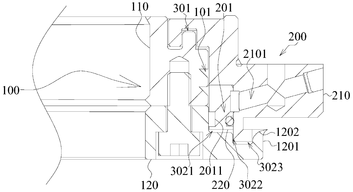
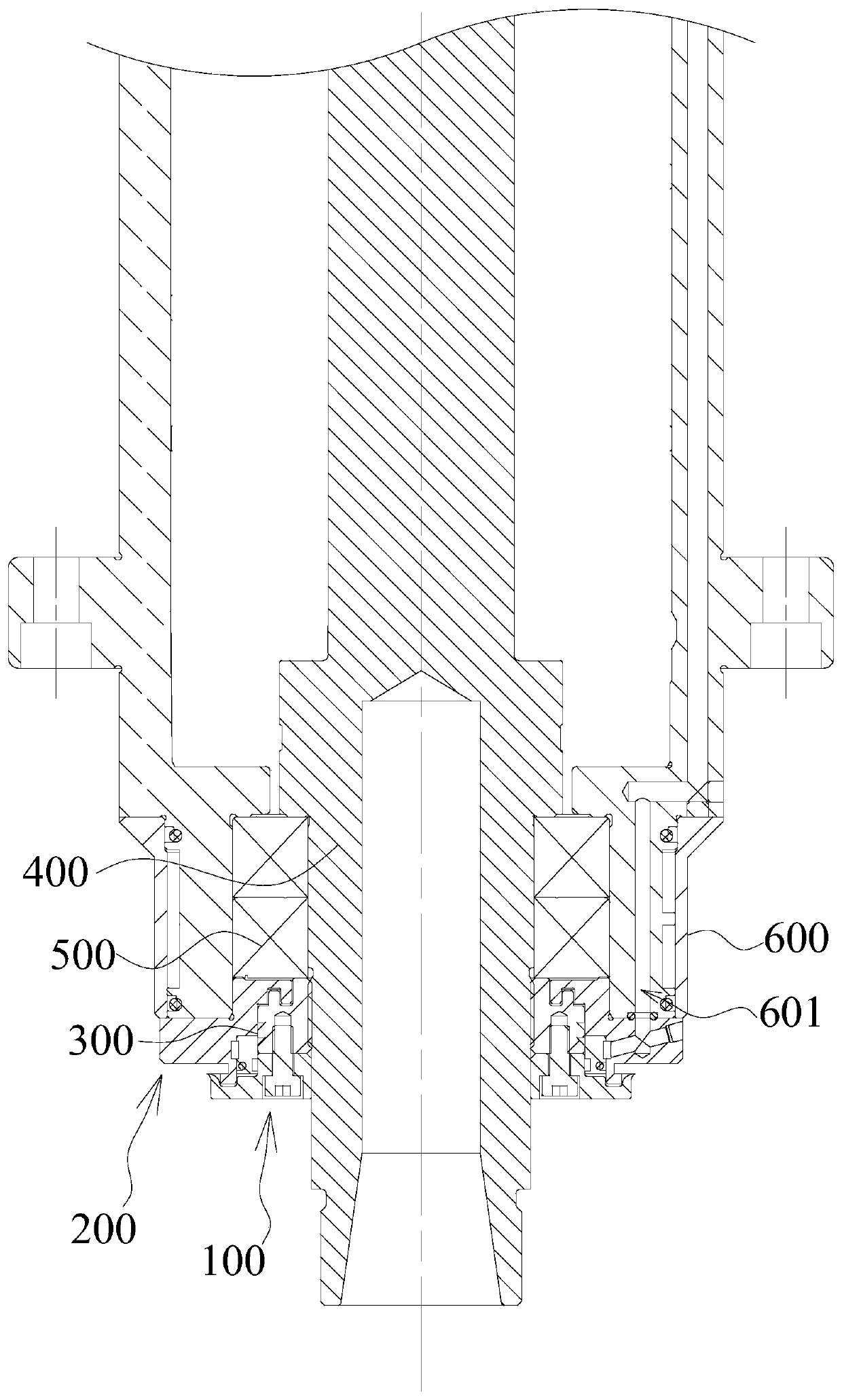
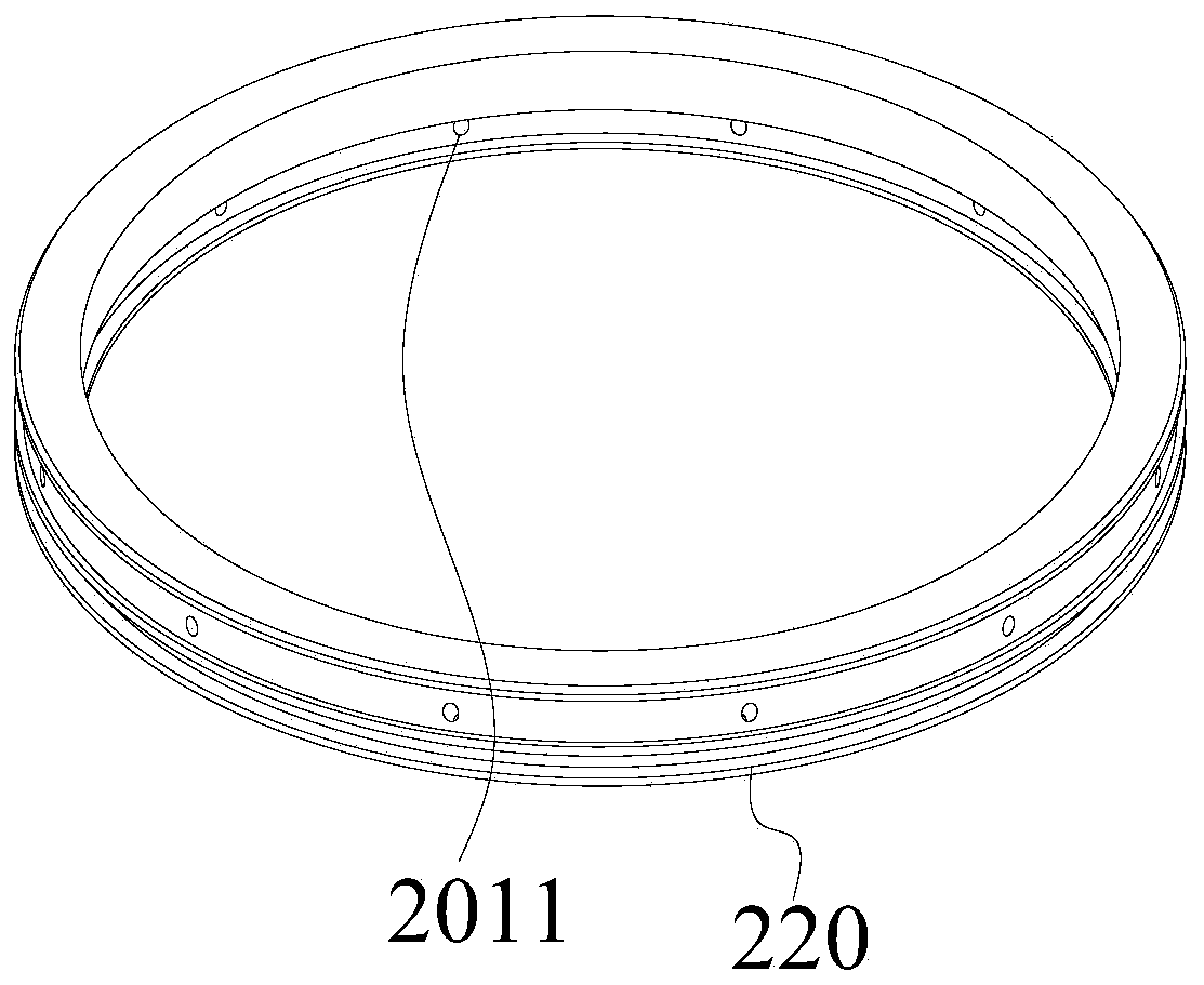
[0038] Such as Figure 1~5 As shown, this embodiment provides a bearing sealing structure, including a lower cover 200, a locking member 110 and a protective cover 120. The locking member 110 is connected with the protective cover 120 to form a rotating assembly 100. The rotating assembly 100 has an opposite first side and On the second side, th...


PUM


Abstract

The invention discloses a bearing sealing structure and an electric spindle with the same, and belongs to the field of machining tool equipment. The bearing sealing structure comprises a lower cover,a locking member and a protective cover, wherein the locking member is connected with the protective cover to form a rotating component; a clearance passage is formed between the lower cover and the rotating component; the lower cover is provided with a plurality of inclined passages; the inclined passages extend toward a second side face; the side, near to the second side face, of each inclined passage is provided with a first air outlet; each first air outlet communicates to the clearance passage; the rotating component is provided with a chute; the chute is provided with a notch and a sidegroove surface; the side groove surface obliquely extends toward the protective cover; the notch communicates with the clearance passage; and the electric spindle comprises the bearing sealing structure, and further comprises a shaft core, a bearing and a spindle body. By the cooperation of the inclined passages and the chute of the bearing sealing structure, the sealing effect is ensured while alubricating medium in the bearing is prevented from being dried up; and the electric spindle with the sealing structure has the advantages of stable performance and long service life.

Description

technical field [0001] The invention relates to processing machine tool equipment, in particular to a bearing sealing structure and an electric spindle including the bearing sealing structure. Background technique [0002] At present, with the development of modern machinery, the concept of Industry 4.0 has been proposed in the industrial field, and the application range of electric spindles has become wider and wider. The electric spindle is a precision component, which is widely used in high-speed, high-precision machining centers. The core component is the high-speed and precise spindle bearing. Under high-speed operation, any tiny impurities entering the spindle bearing may cause the spindle to vibrate. Even damage to the bearing will affect the working accuracy and life of the spindle. The bearing sealing structure of the electric spindle plays a vital role in the accuracy, reliability and working life of the electric spindle. [0003] However, the existing bearing sea...

Claims


Application Information

Patent Timeline
Patent Type & Authority Applications(China)
IPC IPC(8): F16C33/72F16C33/76F16J15/40
Inventor 魏雷宝冯尚雄林盛奕汤秀清
Owner GUANGZHOU HAOZHI ELECTROMECHANICAL
Why Eureka
Try Eureka