
A power management system for electronic equipment

A technology of electronic equipment and power conversion, applied in the direction of emergency power supply arrangement, electrical components, circuit devices, etc., can solve the problem of high cost of embedded systems, and achieve the effect of low gate and low cost

Active Publication Date: 2022-05-27
湖北汇程信息技术有限公司
View PDF4 Cites 0 Cited by
  • Summary
  • Abstract
  • Description
  • Claims
  • Application Information

AI Technical Summary

Problems solved by technology

Embedded systems are costly and have high technical content (such as programming) and are not suitable for small electronic devices

Method used


Image

  • A power management system for electronic equipment

Examples


Embodiment Construction

[0009] The specific embodiments of the present invention will be further described in detail below with reference to the examples. The following examples are intended to illustrate the present invention, but not to limit the scope of the present invention.

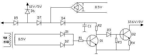
[0010] see figure 1 , an embodiment of the present invention provides a power management system for an electronic device, the system includes a power conversion device, a switching power supply, a control relay, a battery, etc.; wherein, the power conversion device includes a power transformer, and the power transformer is electrically connected to the electronic device , the power conversion device is used to convert the commercial power into the voltage required by the electronic equipment, such as 5V, 12V, etc.; more specifically, it includes a power transformer, a rectifier filter circuit, a voltage regulator circuit, etc., and the power transformer includes a primary winding and at least one secondary The secondary w...


PUM


Abstract

The invention relates to a power management system for electronic equipment, belonging to the technical field of power management. The system includes a power conversion device, a switching power supply, a control relay and a battery, the power conversion device and the switching power supply are electrically connected to the mains, and the switching power supply, the control relay and the battery are electrically connected in turn; the system also includes a power monitoring device , the power conversion device includes a power transformer, and the power monitoring device includes a secondary winding, a triode Q1, a triode Q2, a bridge rectifier circuit T, a diode D1-D7, a resistor R1-R4 and a capacitor C1, and the secondary winding It is coupled with the main winding of the power transformer for voltage reduction, and the secondary winding outputs to the bridge rectifier circuit T and diodes D1-D2. The system can realize power management through basic components such as diodes, transistors, resistors and capacitors.

Description

technical field [0001] The present invention relates to the technical field of power management, in particular to a power management system for electronic equipment. Background technique [0002] In the prior art, in order to ensure that the electronic equipment can continue to work in the state of power failure, a group of batteries is generally added to the electronic equipment as a backup power supply, and both the batteries and the commercial power are electrically connected to the electronic equipment. In the case of charging, the commercial power converts 220V into a low voltage to charge the battery through the switching power supply, and a control relay will be set between the switching power supply and the battery to control charging and discharging. In the prior art, the control relay is usually controlled by a single-chip microcomputer. The single-chip microcomputer is electrically connected to the control terminal of the control relay through a driving circuit or...

Claims


Application Information

Patent Timeline
Patent Type & Authority Patents(China)
IPC IPC(8): H02J9/06
Inventor 周旭宏
Owner 湖北汇程信息技术有限公司
Learn More