A novel remote switch control device

A technology of control devices and switches, applied in the direction of selection devices, data exchange networks, digital transmission systems, etc., can solve problems such as waste of electric energy, impact on the service life of switches, low efficiency, etc., to reduce operating costs, broad market prospects and application prospects , The effect of reducing power consumption

Inactive Publication Date: 2019-05-03
JIANGSU CLOUD FACTORY INFORMATION TECH CO LTD
View PDF5 Cites 2 Cited by
  • Summary
  • Abstract
  • Description
  • Claims
  • Application Information

AI Technical Summary

Problems solved by technology

[0003] At present, when controlling the switch, a special CONSOLE line is usually required to adapt to the CONSOLE port on the computer, so that the configuration and control of the switch can be realized. In the same intranet, if the technician is far away from the switch, it is impossible. Immediately control and configure the switch. This kind of switch control method is inefficient and has areas to be improved.
[0004] The patent application number "201721209039.X" previously applied by our company solves some of the above problems, but this kind of industrial switch is not suitable for mounting on the required occasions with the back
And with the rapid development of modern enterprise automation technology, the number of switches required for its production network is also increasing day by day. Since the switches themselves do not have the function of power control, the switches usually work continuously when no one is using them.
In this way, a large amount of electric energy is wasted; the other is long-term use, which also has a certain impact on the service life of the switch itself.

Method used


Image

  • A novel remote switch control device
  • A novel remote switch control device
  • A novel remote switch control device

Examples


Embodiment 1

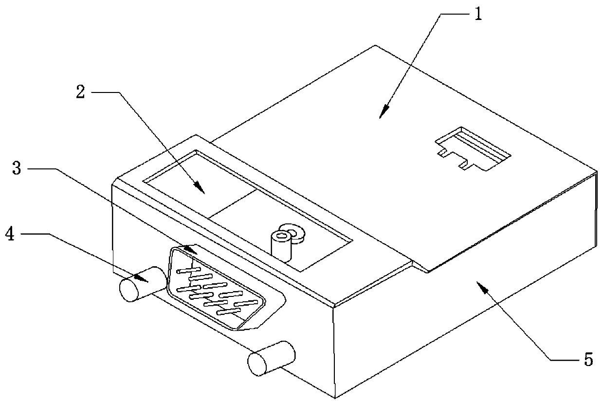
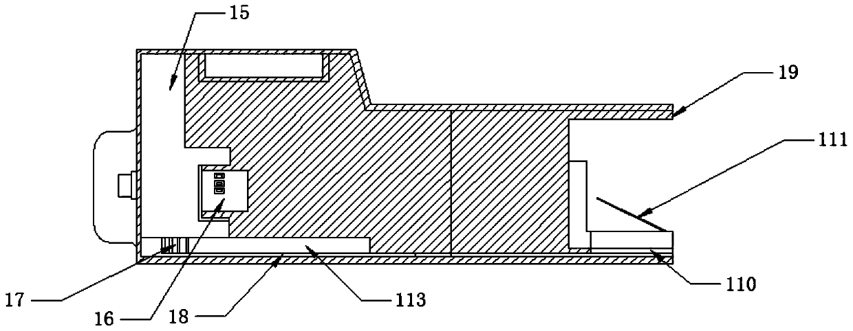
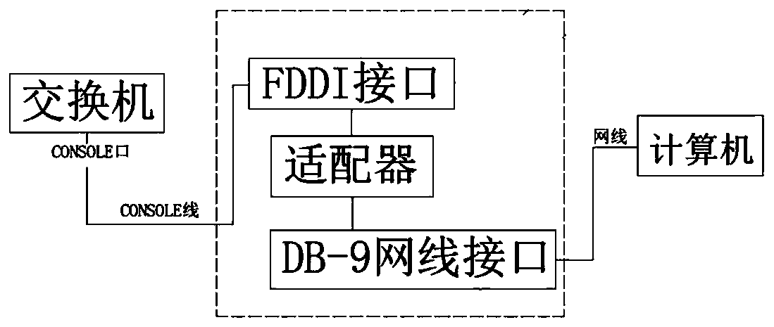
[0036] figure 1 — Figure 4 As shown, a multifunctional remote switch control device includes a housing 1, an FDDI interface 3, a network cable interface 19 and a remote power control system; Side plate 5, the projected area of ​​described panel and described backboard are equal, and described panel and described backboard are parallel, and the distance between described panel and described backboard is less than the shortest side length of described backboard; An anti-interference magnetic ring is fixedly installed on the outer surface around the panel; the FDDI interface is arranged on the side of the housing, and one side of the FDDI interface 3 is embedded in the housing 1, and is connected to the housing The body 1 is fixedly connected, and one side of the FDDI interface 3 is provided with an adapter 15, and the side of the adapter is provided with an optical current isolation ring 16, and the optical isolation current ring 16 is nested on the adapter 15, and is connecte...


PUM


Abstract

The invention discloses a novel remote switch control device. The novel remote switch control device comprises a shell, an FDDI interface, a network cable interface and a remote power supply control system, Wherein the shell is formed by combining plates; each plate comprises a panel, a back plate and a plurality of side plates; anti-interference magnetic rings are fixedly mounted on the outer surfaces of the peripheries of the panels; The FDDI interface is arranged on the side surface of the shell; wherein one side of the FDI interface is embedded in the shell and is fixedly connected with the shell, an adapter is arranged on one side of the FDI interface, the network cable interface is arranged on the opposite side of the FDI interface; the remote power supply control system comprises acontrol module, a signal transmitting module, a signal receiving module and a power supply switch control module. The switch can adapt to more application occasions; The wireless remote control switchhas the advantages of being remarkable in efficiency advantage and simplicity and convenience, remote control over the switch is achieved, the power source of the switch can be automatically switchedon and switched off according to the working time period, remote operation can be executed by receiving wireless remote control signals, power consumption can be greatly reduced, and the enterprise operation cost is reduced.

Description

technical field [0001] The invention relates to the technical field of switch control, in particular to a novel remote switch control device. Background technique [0002] The so-called switch, which means "switch", is a network device used for electrical (optical) signal forwarding. It can provide an exclusive electrical signal path for any two network nodes connected to the switch. The most common switches are Ethernet switches. Other common ones include telephone voice switches, optical fiber switches, etc., which are collectively referred to as technologies that send the information to be transmitted to the corresponding route that meets the requirements according to the needs of transmitting information at both ends of the communication, using manual or automatic equipment methods. Switches can be divided into WAN switches and LAN switches according to different working locations. A wide-area switch is a device that completes the information exchange function in a co...

Claims


Application Information

Patent Timeline
Patent Type & Authority Applications(China)
IPC IPC(8): H04L12/931H04L12/935H04Q1/02H04Q1/04H04L49/111
Inventor 季黎俊朱永
Owner JIANGSU CLOUD FACTORY INFORMATION TECH CO LTD
Why Eureka
Try Eureka