Crankshaft intersecting oil hole deburring tool and using method thereof

A technique for removing hair and oil holes, which is applied in the field of tools for removing burrs from intersecting oil holes of crankshafts, can solve the problems of affecting the life of the crankshaft, high cost, easy corrosion, etc., and achieves the effect of improving deburring efficiency, simple production and easy promotion.

Inactive Publication Date: 2019-05-07
桂林福达曲轴有限公司
View PDF8 Cites 1 Cited by
  • Summary
  • Abstract
  • Description
  • Claims
  • Application Information

AI Technical Summary

Problems solved by technology

Electrolytic deburring needs to invest in electrolytic equipment that is not yet popular, and the cost is high. The processing cycle is not faster than manual straight-shank twist drill deburring. In addition, the electrolytic method will change the material and surface quality of the intersecting area of ​​​​the crankshaft oil hole and is easy. Corrosion affects the life of the crankshaft, and customers generally do not agree to use it
And the most commonly used method of deburring through the oil hole of the manual straight handle twist drill, such as image 3 As shown, when the drill bit is drilled through, the burr at the intersection of the oil hole will turn back into another oil channel. Since the drill bit is straight and rigid, it cannot touch the flanging burr at the intersection, so it cannot be removed directly. The oil hole is drilled through, but the burr at the intersection will return to the original oil passage, so the drill can only be repeated from the two oil holes to ensure that the burr is broken during the back and forth drill; the removal effect is poor and the efficiency is low
There is no special deburring tool for intersecting oil holes in the crankshaft in the prior art

Method used


Image

  • Crankshaft intersecting oil hole deburring tool and using method thereof
  • Crankshaft intersecting oil hole deburring tool and using method thereof
  • Crankshaft intersecting oil hole deburring tool and using method thereof

Examples


Embodiment Construction

[0021] Below in conjunction with the accompanying drawings, the present invention will be specifically described with embodiments.

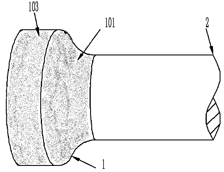
[0022] refer to figure 1 , a tool for removing burrs from crankshaft intersecting oil holes, comprising a cylindrical cutter bar 2 and a cutter head 1 arranged at one end of the cutter bar 2,

[0023] Cutter head 1 is made up of cylindrical cutter body 103 and concave curved surface cutter body 101, and the axis of cylindrical cutter body 103 coincides with the axis of cutter bar 2, and the radius of cylindrical cutter body 103 is greater than cutter bar 2 radius, and the cylindrical surface of cylindrical cutter body 103 is One end of the concave curved cutter body 101 is connected to the cylindrical cutter body 103, and the other end is connected to the cutter bar 2. The concave curved cutter body 101 is surrounded by two end faces and the working curved surface between the two end faces. The working curved surface is a concave rotating surfa...


PUM


Abstract

The invention belongs to the field of engine crankshaft machining, and particularly relates to a crankshaft intersecting oil hole deburring tool and a using method thereof. The tool comprises a cylindrical tool bar and a tool head arranged at one end of the tool bar; the tool head is composed of a cylindrical tool body and an inwards-concave curved surface tool body; the inwards-concave curved surface tool body is composed of two end surfaces and a working curved surface located between the two end surfaces in a surrounding mode, one end of the inwards-concave curved surface tool body is connected with the cylindrical tool body, and the other end of the inwards-concave curved surface tool body is connected with the tool bar; the working curved surface is an inwards-concave rotating curvedsurface, and the radius of an arc is equal to the difference between the radius of the cylindrical tool body and the radius of the tool bar; the working cylindrical surface, the working curved surfaceand the tool bar cylindrical surface are in smooth connection in sequence; and the working cylindrical surface and the working curved surface are both subjected to roughening surface treatment. The using method of the tool comprises the step that burs at the corner of an oil hole are subjected to rotational ablation removal through the working curved surface of the tool head. The tool has the technical effects of being easy to machine and high in intersecting oil hole deburring efficiency.

Description

technical field [0001] The invention belongs to the field of engine crankshaft processing, and in particular relates to a tool for removing burrs from intersecting oil holes of the crankshaft and a use method thereof. Background technique [0002] The crankshaft is one of the core parts of the engine, and maintaining the lubrication of the crankshaft through the oil delivery of the oil hole in the crankshaft is an important method to ensure the reliable operation of the crankshaft. If the burrs generated in the oil hole during the crankshaft manufacturing process are not removed cleanly, it will easily cause the engine to pull and affect the service life of the engine. The burrs generated during the processing of metal products are generally removed by using the roughened surface of the file head. The working surface of the file head is usually roughened by electroplating high-hardness metal abrasives or opening blade grooves. However, in the field of crankshaft processing,...

Claims


Application Information

Patent Timeline
Patent Type & Authority Applications(China)
IPC IPC(8): B23D79/04
Inventor 夏志成黄学文
Owner 桂林福达曲轴有限公司
Why Eureka
Try Eureka