Deburring equipment for inner hole orifice of tubular workpiece

A technology for removing burrs and workpieces, applied in the field of workpiece processing, can solve the problems of poor deburring quality of tubular workpieces, high labor intensity of operators, and low stability of tubular workpieces, so as to improve deburring efficiency and quality, and improve The effect of deburring quality and reducing labor intensity

Inactive Publication Date: 2018-11-20
芜湖瑞德机械科技有限公司
View PDF1 Cites 3 Cited by
  • Summary
  • Abstract
  • Description
  • Claims
  • Application Information

AI Technical Summary

Problems solved by technology

[0003] The purpose of the present invention is to solve the problems of low automation level, high labor intensity of operators, low stability of tubular workpieces in the deburring process, poor deburring quality of tubular workpieces, and poor application range in the existing tubular workpieces. For small problems, provide a deburring of the inner hole of the tubular workpiece with reasonable structure design, high automation level, low labor intensity of the operator, good deburring quality, high work efficiency, good deburring quality of the tubular workpiece, and wide application range equipment

Method used


Image

  • Deburring equipment for inner hole orifice of tubular workpiece
  • Deburring equipment for inner hole orifice of tubular workpiece
  • Deburring equipment for inner hole orifice of tubular workpiece

Examples


Embodiment 1

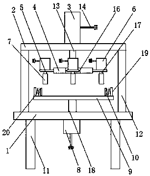
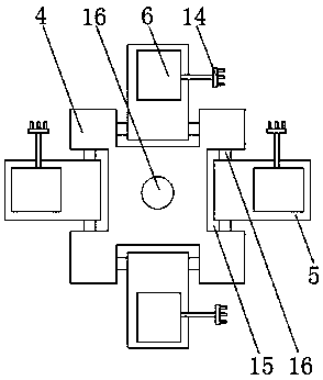
[0017] as attached Figure 1-3 As shown, a device for deburring the inner hole of a tubular workpiece includes an operating table 1, a top plate 2, a cylinder 3, a fixing plate 4, an adjusting plate 5, a grinding motor 6, a grinding shaft 7, a motor 2 8, and a bearing plate 9 And fastening plate 10, it is characterized in that, described console 1 is arranged on support 11, and is provided with vertical plate 12 on console 1, and described top plate 2 is arranged on vertical plate 12, and described air cylinder 3 is set on the top plate 2, and a power cord 14 and a piston rod 13 are set on the cylinder 3, the fixed plate 4 is set on the piston rod 13, and a connecting groove 15 is set on the fixed plate 4, the described Adjusting plate 5 is arranged in connecting groove 15 by connecting shaft 16, and described grinding motor 6 is arranged on adjusting plate 5, and is provided with drive shaft one 17, power cord 14 on grinding motor 6, described grinding shaft 7 It is arranged...

Embodiment 2

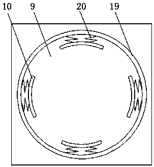
[0022] as attached Figure 4 As shown, a device for deburring the inner hole of a tubular workpiece includes an operating table 1, a top plate 2, a cylinder 3, a fixing plate 4, an adjusting plate 5, a grinding motor 6, a grinding shaft 7, a motor 2 8, and a bearing plate 9 And fastening plate 10, it is characterized in that, described console 1 is arranged on support 11, and is provided with vertical plate 12 on console 1, and described top plate 2 is arranged on vertical plate 12, and described air cylinder 3 is set on the top plate 2, and a power cord 14 and a piston rod 13 are set on the cylinder 3, the fixed plate 4 is set on the piston rod 13, and a connecting groove 15 is set on the fixed plate 4, the described Adjusting plate 5 is arranged in connecting groove 15 by connecting shaft 16, and described grinding motor 6 is arranged on adjusting plate 5, and is provided with drive shaft one 17, power cord 14 on grinding motor 6, described grinding shaft 7 It is arranged o...


PUM


Abstract

The invention discloses deburring equipment for an inner hole orifice of a tubular workpiece. The deburring equipment comprises an operating table, a top plate, an air cylinder, a fixing plate, regulating plates, grinding motors, grinding shafts, a motor II, a bearing plate and a fastening plate. The deburring equipment is characterized in that the operating floor is arranged on a bracket; the topplate is arranged on stand plates; the air cylinder is arranged on the top plate; the fixing plate is arranged on a piston rod; the regulating plates are arranged in connecting grooves through connecting shafts; the grinding motors are arranged on the regulating plates; the grinding shafts are arranged on transmission shafts I; and the motor II is arranged on the operating table. The multiple regulating plates are arranged on the fixing plate of the piston rod of the air cylinder, the grinding motors are arranged on the regulating plates, the grinding shafts are arranged on the transmission shafts I of the grinding motors, and the inner hole orifice of the tubular workpiece on the bearing plate can be subjected to deburring through the grinding shafts, so that the deburring efficiency ofthe tubular workpiece is improved.

Description

technical field [0001] The invention relates to the technical field of workpiece processing, in particular to a device for deburring the inner hole of a tubular workpiece. Background technique [0002] During the processing of the tubular workpiece, burrs will be generated on the edge of the inner hole. If the burrs are not removed, it will not only reduce the product quality of the tubular workpiece, but also cause harm to the operator and reduce the safety performance. For example, the application number is 201710423825.8 The patent discloses a deburring machine for the inner hole of a circular tubular workpiece, which solves the problem of inconvenient operation of the deburring machine, but it has the disadvantages of low automation level, high labor intensity of the operator, and the deburring process of the tubular workpiece. The disadvantages of low stability, poor deburring quality of tubular workpieces, and small application range. Contents of the invention [00...

Claims


Application Information

Patent Timeline
Patent Type & Authority Applications(China)
IPC IPC(8): B24B9/00B24B27/00B24B41/04B24B41/06B24B41/02
CPCB24B9/00B24B27/0007B24B27/0076B24B41/02B24B41/04B24B41/067
Inventor 李刚汪小杰
Owner 芜湖瑞德机械科技有限公司
Why Eureka
Try Eureka