One-circle and double-grinding chamfer deburring machine and deburring method thereof

A deburring machine and deburring technology, applied in the direction of machine tools, grinders, abrasives, etc. suitable for grinding the edge of workpieces, can solve the problems of low grinding efficiency, achieve improved deburring efficiency, convenient polishing and deburring, and easy operation Effect

Active Publication Date: 2015-01-07
HANGZHOU XIANGSHENG ABRASIVE MACHINE MFG
View PDF2 Cites 3 Cited by
  • Summary
  • Abstract
  • Description
  • Claims
  • Application Information

AI Technical Summary

Problems solved by technology

[0004] The shortcomings of the above-mentioned background technology: the annular grinding belt adopts the way of installing the grinding head on the front, so the grinding head of the machine can only be arranged vertically, and the workpiece can only be polished once in one-way passage, and the grinding efficiency is low

Method used


Image

  • One-circle and double-grinding chamfer deburring machine and deburring method thereof
  • One-circle and double-grinding chamfer deburring machine and deburring method thereof
  • One-circle and double-grinding chamfer deburring machine and deburring method thereof

Examples


Embodiment 1

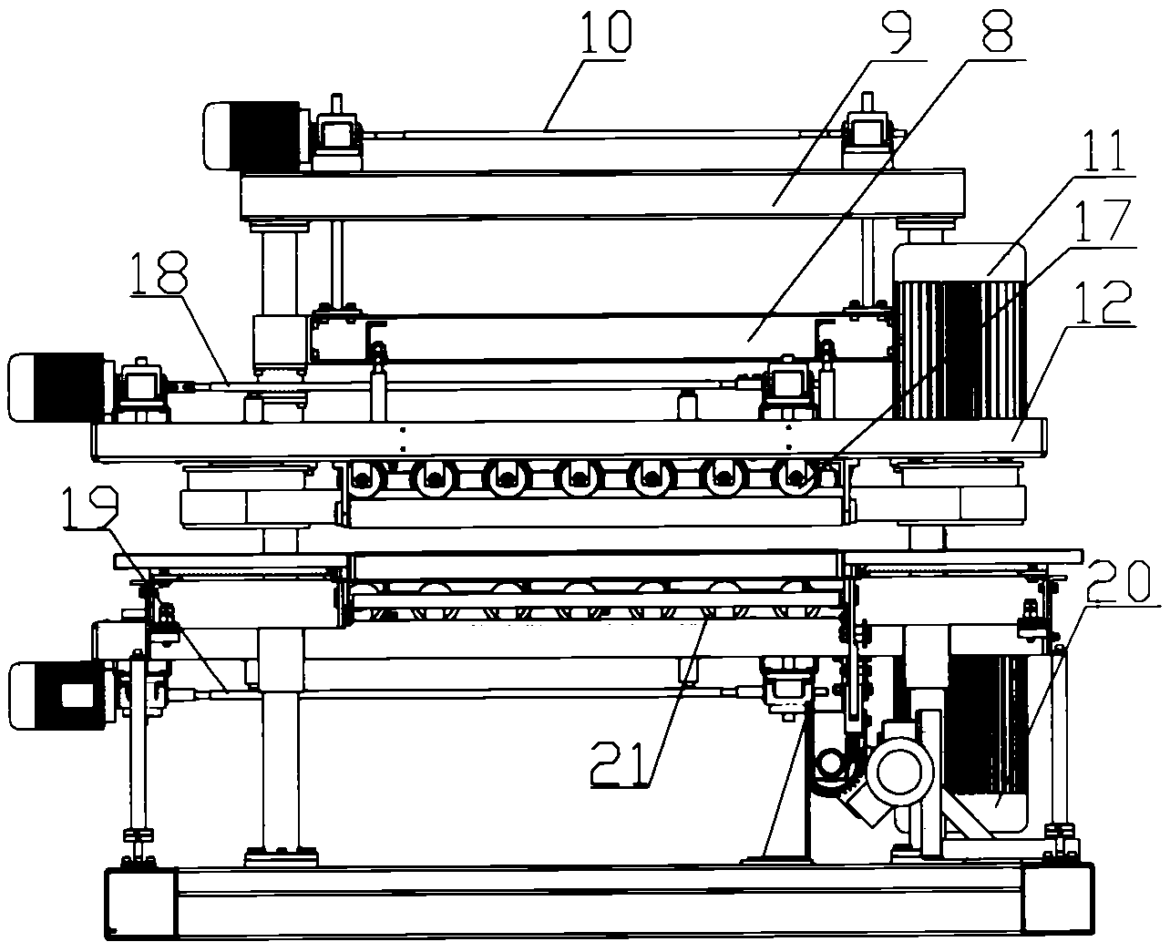
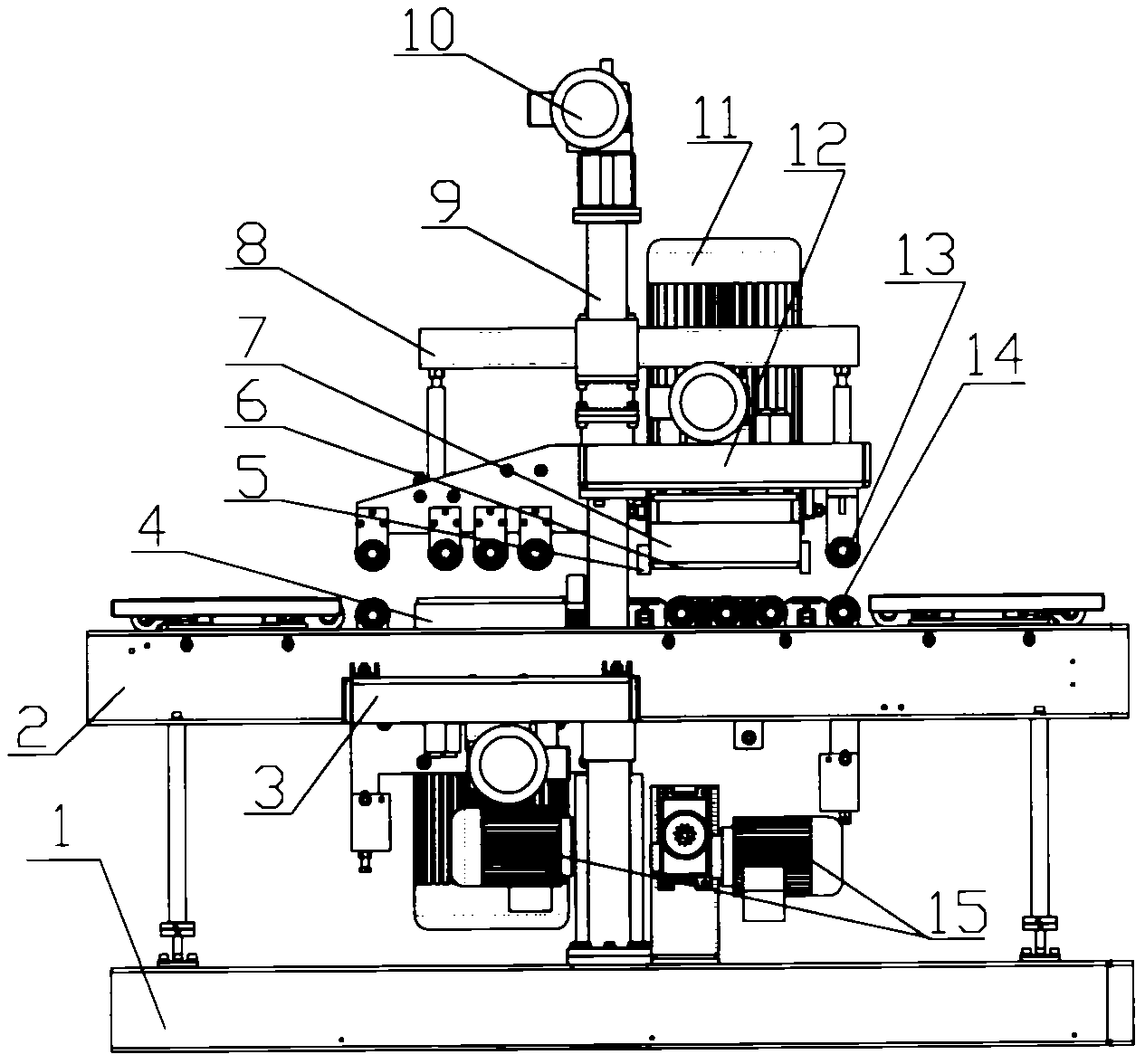
[0017] Embodiment 1: with reference to attached figure 1 . A chamfering and deburring machine with one circle and two grindings, which includes a chamfering and deburring machine, in which the frame 1 and the workbench 2 are fixedly connected by four support columns, and the grinding head gantry 9 Through the workbench 2, its lower end is fixedly connected with the frame 1, the upper brush plate 12 is set on the column of the grinding head gantry 9 and the upper brush plate 12 is driven by the motor 10 on the grinding head gantry 9 through the lifting mechanism 8 8 Drive the upper brush plate 12 to lift up and down along the column, the upper active drum 6 and the upper passive drum 6 are installed on the upper brush plate 12 and the upper active drum 6 is driven by the upper grinding head motor 11 located on the upper brush plate 12, and the upper The grinding belt 7 is horizontally sleeved on the transmission wheel formed by the upper driving drum 6 and the upper passive dr...

Embodiment 2

[0018] Embodiment 2: On the basis of Embodiment 1, a deburring method of a round two grinding chamfering and deburring machine is started. (1) The upper grinding head motor 11 drives the upper grinding head to rotate by driving the upper driving drum to drive the upper grinding head The belt 7 rotates horizontally; (2) the lower grinding head motor 20 drives the lower driving drum to rotate and drives the lower grinding belt 4 to rotate horizontally; When the passage of the upper grinding belt 7 rotates once a week, the upper abrasive block 5 fixed on the upper grinding belt 7 is under the action of the upper grinding belt pressing wheel set 17, and the upper abrasive block is in elastic contact with the surface of the workpiece. Driven by the head motor 11 and the upper driving drum, the polishing and deburring of the front of the workpiece is completed for the second time. At this time, the lower grinding belt 7 located below the workpiece rotates once under the drive of the ...


PUM


Abstract

The present invention relates to a one-circle two-chamfer deburring machine and a deburring method comprising the following steps after starting up: (1) The upper wheelhead motor drives the upper grinding belt to rotate horizontally (2) the lower wheelhead motor drives the lower grinding belt to rotate horizontally and (3) when a deburred workpiece goes through a passage formed by the active feeding roller row and the upper grinding belt, an upper abrasive block elastically contacts surface of the workpiece and, under the drive of the upper wheelhead motor and the upper active drum, polishes and deburrs the front side of the workpiece twice; the lower abrasive block elastically contacts the surface of the workpiece and, under the drive of the lower wheelhead motor and the lower active drum, polishes and deburrs the back side of the workpiece twice.

Description

[0001] The invention relates to a deburring machine and a deburring method in which a grinding belt rotates once, and an abrasive block on the grinding belt can complete secondary polishing on the surface of a workpiece, and belongs to the field of deburring machine manufacturing. Background technique [0002] DE10320295A1 patent discloses the annular grinding belt. In terms of structural design, the annular grinding belt is composed of an annular grinding base belt and a plurality of grinding heads. The plurality of grinding heads are vertically fixed on the surface of the annular grinding base belt. Multiple grinding heads are driven circularly. [0003] CN101262980B, title "deburring or grinding device for strip or plate metal workpiece", the device has at least one processing unit, and the processing unit has a guiding processing element in a direction oblique or perpendicular to the feeding direction of the workpiece A rotary drive that traverses the area of ​​the workpie...

Claims


Application Information

Patent Timeline
Patent Type & Authority Patents(China)
IPC IPC(8): B24B21/12
CPCB24B9/002B24B21/008B24D11/00B24B27/0076B24B21/12B24B27/0069
Inventor 陈勇奇
Owner HANGZHOU XIANGSHENG ABRASIVE MACHINE MFG
Why Eureka
Try Eureka