Al technical title is built by PatSnap Al team. It summarizes the technical point description of the patent document.
A technology for electric vehicles and charging piles, which is applied in electric vehicle charging technology, electric vehicles, charging stations, etc., can solve the problems of large area and installation cost of charging piles, large space occupied, and waste of space, so as to reduce the occupation of electric vehicles. The effect of land area, prevention of safety hazards, and reduction of labor force
Inactive Publication Date: 2017-11-03
广州市双岛科技有限公司
View PDF0 Cites 15 Cited by
Summary
Abstract
Description
Claims
Application Information
AI Technical Summary
This helps you quickly interpret patents by identifying the three key elements:
Problems solved by technology
Method used
Benefits of technology
Problems solved by technology
However, these charging piles generally have disadvantages: the area of the charging pile and the installation cost are large, the charging pile is fixed, and it takes up a lot of space when it is not in use, there is a waste of space, and it is easy to touch and cause electric shock accident happened
Method used
Image
Click on the blue label to locate the original text in one second.
Reading with bidirectional positioning of images and text.
Examples
Embodiment Construction
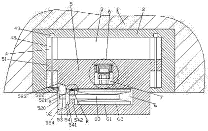
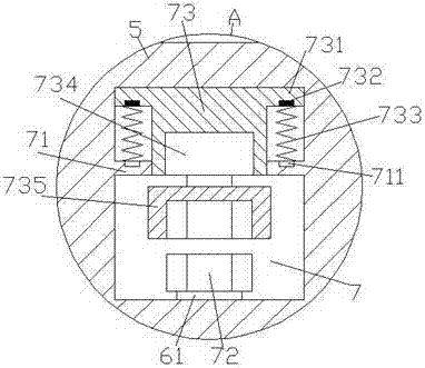
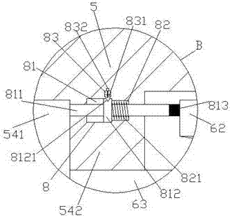
[0022] Such as Figure 1-Figure 6 As shown, an electric vehicle charging pile of the present invention includes a wall top wall 1 and a fixing seat 2 embedded in the wall top wall 1, and the inner bottom of the fixing seat 2 is provided with an accommodation cavity 3, and the accommodation cavity 3 is provided with a movable telescopic part 5, and an operating area 52 is provided in the outer wall of the left side of the movable telescopic part 5, and the inner engaging groove 54 of the movable telescopic part 5 on the right side of the operating area 52, and the right side of the engaging groove 54 A first cavity 6 is provided inside the movable telescopic member 5 on the side, and a first partition 542 is provided between the first cavity 6 and the joint groove 54 . The movable telescopic member 5 is provided with a second cavity 7, the second cavity 7 is provided with a first partition 71, and the second cavity 7 above the first partition 71 is provided with a movable Prot...
PUM
Abstract
The invention discloses a charging pile of an electric automobile. The charging pile of the electric automobile comprises a wall top wall and a fixed seat inlaid in the wall top wall, a containing cavity is formed in the bottom of the interior of the fixed seat, a movable telescopic piece is arranged in the containing cavity, and an operating zone is arranged in the outer wall of the left side of the movable telescopic piece; a joint trough is formed in the position, on the right side of the operation zone, of the movable telescopic piece, a first cavity is formed in the position, on the right side of the joint trough, of the movable telescopic piece, a first separation plate is arranged between the first cavity and the joint trough, a second cavity is formed in the position, above the first cavity, of the movable telescopic piece, a first separation plate is arranged in the second cavity, and a movable protruding block is arranged in the position above the first separation plate, of the second cavity; and protruding blocks are arranged at the tops of the two sides of the movable protruding block, magnet bodies are arranged in the bottoms of the protruding blocks, electromagnetic coil devices are arranged at the positions, corresponding to the magnet bodies, of the top of the first separation plate, first springs are arranged between the electromagnetic coil devices and the magnet bodies, and the bottom of the movable protruding block penetrates through the first separation plate. The charging pile of the electric automobile is simple in structure, small in occupied area, and can prevent a charging gun head from being exposed externally to result in potential safety hazards.
Description
technical field [0001] The invention relates to the technical field of new energy electric vehicles, in particular to an electric vehicle charging pile. Background technique [0002] With the increasingly urgent task of energy saving and emission reduction, electric vehicles have been promoted on a large scale. However, in the process of consumption and use of electric vehicles, there is still a lot of room for improvement in the improvement of supporting charging facilities. At present, there are a variety of charging piles on the market, which can effectively solve the charging problem of electric vehicles. However, these charging piles generally have disadvantages: the area of the charging pile and the installation cost are large, the charging pile is fixed, and it takes up a lot of space when it is not in use, there is a waste of space, and it is easy to touch and cause electric shock Accidents happen. Contents of the invention [0003] The technical problem to be...
Claims
Application Information
Patent Timeline
Application Date:The date an application was filed.
Publication Date:The date a patent or application was officially published.
First Publication Date:The earliest publication date of a patent with the same application number.
Issue Date:Publication date of the patent grant document.
PCT Entry Date:The Entry date of PCT National Phase.
Estimated Expiry Date:The statutory expiry date of a patent right according to the Patent Law, and it is the longest term of protection that the patent right can achieve without the termination of the patent right due to other reasons(Term extension factor has been taken into account ).
Invalid Date:Actual expiry date is based on effective date or publication date of legal transaction data of invalid patent.