Real-time calculation method of position and attitude of large aperture antenna panel based on edge sensor

An antenna panel and real-time computing technology, applied in antennas, navigation computing tools, instruments, etc., can solve problems such as limited distribution of artificial satellites, short wavelength observation bands, and difficulty in meeting requirements

Active Publication Date: 2020-09-08
XIDIAN UNIV
View PDF6 Cites 0 Cited by
  • Summary
  • Abstract
  • Description
  • Claims
  • Application Information

AI Technical Summary

Problems solved by technology

The signal strength of celestial sources is relatively weak, it is difficult to meet the requirements, which may result in insufficient measurement resolution
However, artificial satellites have strong signals, and using artificial satellites as signal sources can generally obtain high aperture and phase resolution. However, the distribution of artificial satellites is very limited, and effective measurements can only be achieved at limited angles, which cannot meet the needs of large radio telescopes. Requirements for Surface Deformation Measurements at Arbitrary Attitudes
The use of near-field holography requires the installation of signal towers and reference antennas. The method of signal towers can indeed theoretically solve multiple attitude measurement problems, but the height of signal towers required by the size of large radio telescopes cannot be achieved at present, so near Field holographic measurement is also difficult to meet the measurement requirements
[0004] In order to overcome the shortcomings of the above two types of antenna reflective surface shape measurement methods, such as not being real-time, heavy, and unable to be measured from any angle, an edge sensor detection method is proposed to realize real-time splicing detection and adjustment in the process of batch panel observation , in order to achieve a shorter wavelength observation band and achieve better antenna technical indicators

Method used


Image

  • Real-time calculation method of position and attitude of large aperture antenna panel based on edge sensor
  • Real-time calculation method of position and attitude of large aperture antenna panel based on edge sensor
  • Real-time calculation method of position and attitude of large aperture antenna panel based on edge sensor

Examples


Embodiment Construction

[0079] The present invention will be described in detail below in conjunction with the accompanying drawings and specific embodiments, where the schematic embodiments and descriptions of the present invention are used to explain the present invention, but not to limit the present invention.

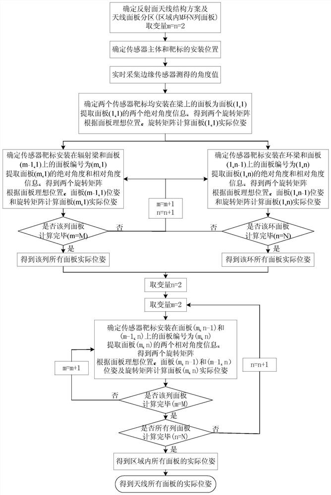
[0080] refer to figure 1 , the present invention is a real-time calculation method for the position and attitude of a large-diameter antenna panel based on an edge sensor, and the specific steps are as follows:

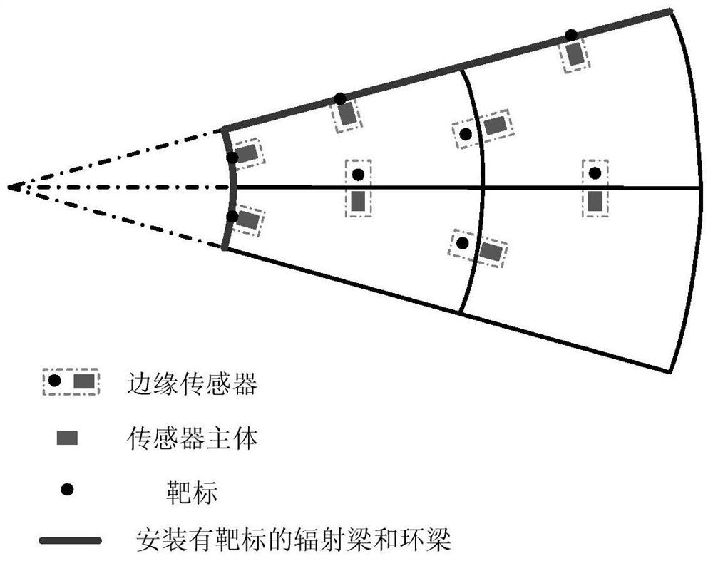
[0081] Step 1. Determine the structure scheme of the large-aperture reflector antenna and the partition of the antenna panel

[0082] 1.1 Determine the structural parameters of the reflective surface of the large-aperture antenna, including the reflective surface aperture and focal length;

[0083] 1.2 Determine the panel block scheme including the total number of antenna reflective panels, the number of reflective panel rings, the number of panel columns, and the block scheme s...


PUM


Abstract

The invention discloses a real-time calculation method of positions and postures of large-diameter antenna panels based on edge sensors. The real-time calculation method comprises the steps: a large-diameter reflecting surface antenna structure scheme is determined, and an antenna is divided into a plurality of areas in the directions of a radiation beam and a ring beam; the mounting positions ofedge sensor main bodies and targets are determined; angle values measured by the edge sensors are collected in real time; the sensor target mounting panels are sequentially determined, and the actualpositions and postures of the panels are calculated; the actual positions and postures of all the panels in the areas are obtained; and the steps are repeated to calculate the actual positions and postures of all the panels. The angle sensors mounted at the edges of the panels can be utilized to read to calculate the actual positions and postures of the deformed large-diameter antenna panels in real time, the basis is provided for active adjustment of the subsequent reflecting surface antenna panels, and thus the electrical performance and pointing accuracy of the antenna under observation service are guaranteed.

Description

technical field [0001] The invention belongs to the technical field of antennas, in particular to a method for real-time calculation of the position and posture of a large-diameter antenna panel based on an edge sensor. The invention can be used for real-time calculation of the position and attitude of the large-diameter antenna panel, laying a foundation for the active adjustment of the subsequent reflector antenna panel, so that the antenna performance can be optimized. Background technique [0002] As the antenna aperture becomes larger and the operating frequency is higher and higher, the antenna structure becomes more and more complex, making the antenna aperture efficiency and pointing more and more sensitive to structural deformation. At this time, the traditional compensation method can no longer meet the requirements of the antenna electrical performance. Requirements, the shape of the main surface must be adjusted, that is, to realize the active adjustment of the m...

Claims


Application Information

Patent Timeline
Patent Type & Authority Patents(China)
IPC IPC(8): G01C21/20G01C1/00G06F17/10H01Q19/12
Inventor 王从思雷婷严粤飞王艳连培园薛松许谦王娜张洁项斌斌段玉虎杜彪
Owner XIDIAN UNIV
Why Eureka
Try Eureka