A topological structure updating system and method for stream processing

A technology of topology structure and update method, applied in the field of data processing, can solve the problem that the big data stream processing architecture is not suitable for online topology update, etc., and achieve the effect of realizing hot deployment, solving online topology update, and realizing online update.

Active Publication Date: 2019-05-07
BEIJING GRIDSUM TECH CO LTD
3 Cites 4 Cited by

AI-Extracted Technical Summary

Problems solved by technology

[0005] The embodiment of the present invention provides a stream processing topology update system and method to solve t...

Method used

As shown in Figure 3, the logical structure of the topology update system provided by the application can be divided into two layers, the upper layer is the task manager 10, that is, the Master main control point, responsible for managing system resources, monitoring the system, For task management and scheduling, it provides various functions such as error recovery, configuration management, and metadata management. As shown in Figure 3, the above-mentioned task manager 10 can be deployed with multiple instances, and a Leader can be dynamically elected among each instance, while other instances are in the Standby state. When the Leader fails, a new Leader is re-elected to take over the system, ensuring High availability of the system.
Fig. 3 is the structural representation of a kind of optional topology updating system according to the embodiment of the present invention, as shown in Figure 3, the logical structure of the topology updating system provided by the application can be divided into two layers, and the upper layer is The task manager 10, also known as the Master control point, is responsible for managing system resources, monitoring the system, managing and scheduling tasks, and providing multiple functions such as error recovery, configuration management, and metadata management. As shown in Figure 3, the above-mentioned task manager 10 can be deployed with multiple instances, and a Leader can be dynamically elected among each instance, while other instances are in the Standby state. When the Leader fails, a new Leader is re-elected to take over the system, ensuring High availability of the system.
[0045] In an optional embodiment, distributed stream processing is usually expressed in the form of directed acyclic graphs (Directed Acyclic Graphs, DAGs), and DAG nodes are called tasks, which represent the analysis and processing logic of data, The data stream flows from the source to the destination through a series of tasks to complete the pipeline processing. Therefore, DAG is a topological representation of stream work. There are currently many stream processing frameworks, such as Spark...

Abstract

The invention discloses a topological structure updating system and method for stream processing. The system comprises a task manager used for detecting a first state of a first state machine and generating a control message according to the state, wherein the first state is used for triggering a topological structure for stream processing to be managed; The task executor used for receiving the control message; And triggering a second state of a second state machine under the triggering of the control message, and executing an action corresponding to the second state on the topological structure according to the second state. The technical problem that an existing big data stream processing architecture is not suitable for online stream topology updating is solved.

Application Domain

Fault responseSoftware design +2

Technology Topic

Data stream processingStream processing +3

Image

  • A topological structure updating system and method for stream processing
  • A topological structure updating system and method for stream processing
  • A topological structure updating system and method for stream processing

Examples

  • Experimental program(3)

Example Embodiment

[0035] Example 1
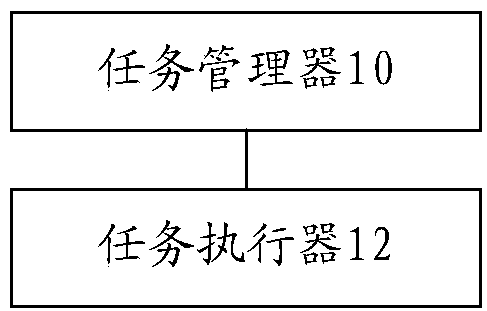
[0036] The embodiment of the present invention provides an embodiment of a stream processing topology update system. figure 2 Is a schematic structural diagram of a topology update system according to an embodiment of the present invention, such as figure 2 As shown, the system includes: a task manager 10 and a task executor 12, among which,
[0037] The task manager 10 is used to detect the first state of the first state machine and generate a control message according to the above state, where the above first state is used to trigger the management of the stream processing topology; the task executor 12 is used to receive The control message; and under the trigger of the control message, the second state of the second state machine is triggered, and an action corresponding to the second state is performed on the topology according to the second state.
[0038] In the embodiment of the present invention, the online update method is used to detect the first state of the first state machine through the task manager, and to generate a control message according to the above state, wherein the above first state is used to trigger the stream processing The topological structure is managed; the task executor is used to receive the above-mentioned control message; and under the trigger of the above-mentioned control message, trigger the second state of the second state machine, and execute the above-mentioned topological structure and the above-mentioned second state according to the second state. The action corresponding to the state achieves the purpose of completing the online change of stream processing without restarting the application, thus realizing the technical effect of hot deployment and online updating of stream processing logic, and thus solves the unsuitability of the existing big data stream processing architecture Technical problem of online topology update.
[0039] In an optional embodiment, the above task executor includes: a virtual machine process; the above task includes: an Actor in the Akka system.
[0040] It should be noted that "Akka", as a message-driven tool and runtime framework suitable for high-concurrency distributed environments, provides an Actor-based programming model. Actor is the smallest stateful computing unit in Akka, which completes different actions and responses based on the type of input message. Actors can define multiple Receives, which respectively represent the set of message types and response actions that the Actor can receive, and switch between different Receives through the become call of the Akka context Context, thereby realizing different processing behaviors of the Actor.
[0041] In an optional embodiment, the foregoing actions include at least one of the following: addition of nodes in the foregoing topology, deletion of nodes, and modification of logical relationships between nodes. Among them, the above-mentioned topological structure includes: a directed acyclic graph DAG.
[0042] image 3 Is a schematic structural diagram of an optional topology update system according to an embodiment of the present invention, such as image 3 As shown, the logical structure of the topology update system provided by this application can be divided into two layers. The upper layer is the task manager 10, that is, the master control point, which is responsible for managing system resources, monitoring the system, and managing and scheduling tasks. Provides multiple functions such as error recovery, configuration management, and metadata management. Such as image 3 As shown, the above-mentioned task manager 10 can be deployed in multiple instances. Each instance can dynamically elect a leader, while other instances are in the Standby state. When the leader hangs up, a new leader is re-elected to take over the system to ensure that the system is high Availability.
[0043] Still as image 3 As shown, the lower layer of the logical structure of the above topology update system can be a task executor, which runs on multiple physical servers in the cluster. Each task executor is a Java virtual machine process that receives task control commands from the Master. The tasks deployed in the virtual machine perform life cycle management and resource allocation.
[0044] It should be noted that the distributed stream processing mode has been developed as a general computing model. It is the continuous analysis and processing of unbounded data and completes the response in seconds or even milliseconds. Since this application focuses on the method of online update of the stream processing topology, in each embodiment, focus is on the functions and implementation of the above-mentioned task manager and task executor.
[0045] In an alternative embodiment, distributed stream processing is usually represented in the form of Directed Acyclic Graphs (DAGs). DAG nodes are called tasks, which represent the analysis and processing logic of data, and the data flow passes through A series of tasks flow from the source point to the end point and complete the pipelined processing. Therefore, DAG is a topological representation of flow work. There are currently many stream processing frameworks, such as Spark, Apache Flink, Storm, etc. Although these systems are different in usage methods and APIs, they essentially analyze submitted applications and convert user processing logic into DAG representation. Then the tasks in the DAG are deployed on the distributed cluster to realize the efficient distribution, processing and aggregation of stream data among task nodes; among them, the application is the basic unit of stream processing submission, and one application corresponds to one DAG representation.
[0046] Through the above-mentioned embodiments of this application, the online update of the stream computing topology is realized based on the Akka state machine, and the online update can be implemented without restarting the application, and the dynamic addition, deletion, and replacement of topology nodes can be implemented, thereby realizing the stream processing logic. Hot deployment and online update, it should be noted that the above implementation scheme has a wide range of application prospects, especially for the occasions where the shutdown is not allowed for 7*24 hours.
[0047] As an optional embodiment, the foregoing first state includes: a first sub-state, a second sub-state, and a third sub-state; wherein: the foregoing first sub-state is used to indicate the state of the current task or to receive the foregoing Update information of the topology; the second sub-state is used to deploy the updated topology; the third sub-state is used to restore the topology to the previous version when the deployment of the topology is abnormal.
[0048] It should be noted that the update information of the above-mentioned topology structure is the topology structure information of the new version.
[0049] In an optional embodiment, the above-mentioned task management may be a functional module of the task manager Master, and each task manager corresponds to one application submission, that is, manages a DAG topology. Functions include hot deployment after DAG change, task status query, task execution process error handling, etc.
[0050] Specifically, the above task manager can be implemented as a state machine, including three states: ready state (the first sub-state above), the recovery state (the second sub-state above), and the dynamic deployment state (the third sub-state above), Figure 4 According to an embodiment of the present invention, an optional structural diagram of the conversion relationship of the sub-states in the first state, such as Figure 4 It shows that the switching between these three states uses the state switching function of the Akka state machine, and the online change of processing behavior can be completed without restarting the application.
[0051] In order to facilitate the understanding of the embodiments of this application, the following specific examples are combined Figure 4 The three sub-states of the above first state are described in detail:
[0052] Ready state: the state that the task has been deployed and is being executed, or that it is initially empty and waiting to receive the DAG topology. Among them, the ready state includes three types of message processing logic, namely onQuery, onError, onNewDag, onQuery handles the task status query; onError handles the received error notification, such as the task executor down or execution error (because the Master in Akka It is the parent node of the task executor, can receive the task executor Stopped and exception messages), and switch the task state to the "recovery state"; onNewDag receives the DAG deployment message, and the message contains the new version of the DAG topology. The processing logic here is: compare the new version of the DAG with the previous version of DAG, and decompose which nodes of the DAG are new nodes, which nodes need to be modified, which nodes need to be deleted, and unaffected nodes do not need Any operation. In the case of new nodes, you can choose to reuse the existing task executor, or choose such as Figure 4 Start a new task executor (depending on the resource scheduling situation) at the "1. New topology DAG" shown, and then execute as Figure 4 The "2. New Topology DAG" shown will switch the state to "Dynamic Deployment Mode".
[0053] Dynamic deployment mode: Stop the existing DAG task node, deploy the new version of the DAG topology, and complete this operation through startDag. "Dynamic deployment state" and "recovery state" share startDag for DAG deployment, but the latest version of DAG is deployed in "recovery state". startDag is the master control of DAG deployment. It applies for resources from the resource manager, queries the task scheduler for the physical deployment plan, and launches, Change, and Stop tasks on different task executors according to the plan, and realizes the deployment of DAG through message interaction . In addition, the dynamic deployment state can also include onQuery and onMessageLoss, where onQuery is used for status query, and onMessageLoss is used for processing such as Figure 4 Show "message lost/task executor stop" and switch to "recovery state".
[0054] Recovery state: indicates that the task execution encounters an exception or the DAG deployment process has a problem, and the state needs to be restored. For example, if the physical server is down, the processing logic throws an exception, the message is lost, the deployment of a DAG task node on a physical server is unsuccessful, etc., at this time, the latest error-free DAG deployment is restored through the "recovery state". Both the "ready state" and the "dynamic deployment state" may switch to the "recovery state". The DAG topology that the former will restore is the DAG topology that has been correctly deployed the last time it enters the "ready state", and the latter refers to the deployment of a new DAG. For the DAG topology that was replaced at the time, the change and deployment of this topology are completed through startDag.
[0055] It should be noted that if resources are unavailable during the execution of startDag, the state will still stay in the "recovery state" at this time, but try to restore a DAG topology that is more advanced in time until a certain deployment is successful or it can be traced back to the DAG. The end of the history chain, that is, when the DAG is empty. The onExecutorError handles the situation that the task executor is down or abnormal during recovery, and the executor is either restarted or the task is stopped according to a predefined strategy.
[0056] This application also provides an optional implementation manner. The task manager is further configured to switch to the second sub-state when the first sub-state receives the update information of the topology structure; in the first sub-state, When the state receives an abnormal notification, it switches from the first sub-state to the third sub-state; and when the deployment of the topology structure is abnormal in the second sub-state, it switches from the second sub-state to the third sub-state status.
[0057] In an optional embodiment, the above-mentioned second state includes: a fourth sub-state, a fifth sub-state, a sixth sub-state, and a seventh sub-state; wherein: the above-mentioned fourth sub-state is used to indicate the above-mentioned current task The execution state of the task in the executor, and when a preset message is received, switch to the fifth sub-state; the fifth sub-state is used to perform a specified operation on the current task, and the specified operation includes: starting the task structure The sixth sub-state is used to start the task in the topology corresponding to the sixth sub-state when the message for starting the task is detected; the sixth sub-state is used to stop All tasks in the above-mentioned topology structure are switched to the above-mentioned fifth sub-state to restore the version before the abnormality of the above-mentioned topology structure.
[0058] As an optional embodiment, the task executor is a child node of the task manager in the Akka tree structure. It receives messages from the task manager to start, change, and stop the execution of tasks. The task manager itself is implemented to include State machine with four states.
[0059] Figure 5 It is a schematic structural diagram of an optional conversion relationship of sub-states in the second state according to an embodiment of the present invention, such as Figure 5 As shown, the above-mentioned second state includes: ACTIVE state (the above-mentioned fourth sub-state), PHASE1 state (the above-mentioned fifth sub-state), PHASE2 state (the above-mentioned sixth sub-state) and RECOVERY state (the above-mentioned seventh sub-state), which are To facilitate the understanding of the embodiments of this application, the following specific examples are combined Figure 4 The four sub-states of the above second state are described in detail:
[0060] ACTIVE state: It is a steady state of the task executor, which means that the start, change or stop operation of the task has been completed. This state can receive StopTask messages and perform stop operations on the corresponding tasks. When receiving a LaunchTasks or ChangeTasks message from the task manager, switch to the "PHASE1" state.
[0061] PHASE1 state: The operations that can be performed in this state include starting tasks, changing task execution parameters, and receiving TaskRegistered messages to track registered tasks. After all tasks have been deployed, the task manager sends a TaskLocationReady message to the task executor, so that the task executor in the "PHASE1" state is switched to the "PHASE2" state. The "PHASE1" state also receives the RestartTasks message from the task manager to restore the DAG topology whose version is dagVersion, and the state switches to the "RECOVERY" state.
[0062] PHASE2 state: similar to a barrier, after receiving the StartAllTasks message of the task manager, it sends a StartTask message to the task that belongs to the current DAG under its management to start the task. The "PHASE2" state also receives the RestartTasks message from the task manager to restore the task whose version is dagVersion, and the state switches to the "RECOVERY" state.
[0063] RECOVERY state: To prepare for restoring the topology of a certain DAG version, this needs to stop all tasks of the current DAG version. When all currently running tasks are stopped (Remain=0), the state switches back to "PHASE1" for deployment of the DAG to be restored. Since the task executor is the parent node of the task in the Akka management structure, it can receive the task termination message TaskStopped, so that it can determine the number of tasks that have not been closed.
[0064] Image 6 It is a schematic diagram of the execution sequence of a task executor starting a task according to an embodiment of the present invention, such as Image 6 As shown, the task executor in the state "PHASE1" receives the start task command from the task manager and executes the LaunchTasks creation task. After the task is created, it registers with the task manager. After the task manager receives the registration, it sends TaskRegistered to the task executor Feedback registration is successful. When all tasks (may be located in multiple task executors) that the task manager needs to create are successfully created and registered, it sends TaskLocationReady messages to all task executors, which causes the task executor to switch from state "PHASE1" to "PHASE2" ". After the task manager has processed the necessary resource accounting, persisted the new version of the DAG representation, and initialized the clock, it sends the message StartAllTasks to the task executor in "PHASE2", and the task executor sends the message StartTask to start the execution of the task. At the same time, its own state is switched to "ACTIVE" to complete the operation of Launch a task.
[0065] Figure 7 Is a schematic diagram of an optional state transition relationship according to an embodiment of the present invention, such as Figure 7 As shown, the task is implemented as an Akka Actor, which contains three states: when the task starts, it sends a RegisterTask message to the task manager to register, and then enters the "waiting for task registration" state; when the task manager's confirmation message TaskRegistered is received, it enters the "waiting task" state. Start” state; when the tasks that the task manager needs to deploy have been started, it sends a StartAllTasks message to the task executor. After the task executor receives the message, it sends a StartTask message to the task. The task enters the “processing message” state. The state task can receive the ChangeTask message to change the operation logic executed by the task.
[0066] Among them, it should be noted that the above tasks can exist in the form of Java Jar, but are not limited to, uploaded to the global storage by submitting the application API or adding and deleting node APIs, with a unique path identifier, and loaded by the task executor that executes the task when it runs. After parsing, the task Actor is created to complete the runtime deployment of the task.
[0067] In an optional embodiment, regarding dynamically adding new nodes, the following API description is given: Since each task node will be assigned a unique Id by the system during DAG deployment, when new nodes and edges need to be added to the DAG, Specify which nodes of the DAG the new edge refers to, the API is as follows:
[0068] addVertext(dag:DAG,upstreamProcessorIds:Array[Id],edges:Array[EdgeDescription],newVertext:VertextDescription,newVersion:Int)
[0069] Among them, the above parameter "dag" indicates the current DAG topology; the parameter "upstreamProcessorIds" indicates which nodes in the dag the newly added node originated from, and an array of type Id; the parameter "edges" indicates an array of type EdgeDescription, where the edges are The logical side of the DAG may correspond to multiple physical event distribution channels after the actual deployment is completed. The parameter "EdgeDescription" means logically describing the distribution logic of the event in these physical distribution channels, such as hash-based or rotation-based, etc.; the parameter newVertext type is VertextDescription, which means the node processing logic, which is parsed from the jar package; the parameter newVersion means The new version number is incremented by 1 each time.
[0070] In another optional embodiment, the execution process of dynamically adding new nodes is as follows: based on the current DAG, the system adds nodes specified in the API to generate a new version of the DAG. At this time, the task manager is in the "ready state". After the onNewDag processing logic receives the new version of the DAG, it will either start a new task executor or use an existing task executor to deploy a new node (depending on the resource scheduling situation), Then switch the task manager state to "dynamic deployment state", startDag applies for resources from the resource manager, requests a deployment plan from the task scheduler, and deploys the DAG node on the task executor (here just deploys a new node , The original unaffected DAG node deployment location remains unchanged), the deployment process on the task executor is as Figure 5 As shown, when the node deployment is completed, the task manager switches back to the "ready state", and the new DAG topology deployment is completed.
[0071] In addition, in an optional embodiment, the application can also dynamically reduce nodes. It should be noted that the process of reducing nodes is similar to dynamically adding new nodes, except that reducing nodes is to stop operation, and the resources occupied by nodes require Recycling. The node here is restricted to the leaf nodes of the DAG, and it is not allowed to delete intermediate nodes. Deleting intermediate nodes may cause multiple DAG disconnections, which will cause some DAG task flows to lose data sources and increase the complexity of system management and implementation.

Example Embodiment

[0072] Example 2
[0073] According to an embodiment of the present invention, an embodiment of a stream processing topology update method is provided. It should be noted that the steps shown in the flowchart of the accompanying drawings can be executed in a computer system such as a set of computer executable instructions. Also, although a logical sequence is shown in the flowchart, in some cases, the steps shown or described may be performed in a different order than here.
[0074] Figure 8 A flow chart of steps of a stream processing topology update method according to an embodiment of the present invention, such as Figure 8 As shown, the method includes the following steps:
[0075] Step S102: Obtain a control message, where the control message is a message generated according to the first state of the first state machine, and the first state is used to trigger the management of the stream processing topology;
[0076] Step S104, triggered by the control message, trigger a second state of the second state machine, and perform an action corresponding to the second state on the topological structure according to the second state.
[0077] In the embodiment of the present invention, an online update method is adopted to obtain a control message, where the control message is a message generated according to the first state of the first state machine, and the first state is used to trigger the flow processing topology. Management; triggered by the above control message, triggers the second state of the second state machine, and executes actions corresponding to the above second state on the above topology according to the second state, so that the stream processing can be completed without restarting the application The purpose of online change is to realize the hot deployment of stream processing logic and the technical effect of online update, thereby solving the technical problem that the existing big data stream processing architecture is not suitable for online topology update.
[0078] In an optional embodiment, the execution subject of the above steps S102 to S104 may be, but not limited to, a task executor. The task executor includes: a virtual machine process; and the above task includes: an Actor in the Akka system.
[0079] It should be noted that "Akka", as a message-driven tool and runtime framework suitable for highly concurrent distributed environments, provides an Actor-based programming model. Actor is the smallest stateful computing unit in Akka, which completes different actions and responses based on the type of input message. Actors can define multiple Receives, which respectively represent the set of message types and response actions that the Actor can receive, and switch between different Receives through the become call of the Akka context Context, thereby realizing different processing behaviors of the Actor.
[0080] In an optional embodiment, the foregoing actions include at least one of the following: adding nodes, deleting nodes, and modifying logical relationships between nodes in the foregoing topology structure. Among them, the above topological structure includes: a directed acyclic graph DAG.
[0081] Such as image 3 As shown, the logical structure of the topology update system provided by this application can be divided into two layers. The upper layer is the task manager 10, that is, the master control point, which is responsible for managing system resources, monitoring the system, and managing and scheduling tasks. Provides multiple functions such as error recovery, configuration management, and metadata management. Such as image 3 As shown, the above-mentioned task manager 10 can be deployed in multiple instances. Each instance can dynamically elect a leader, while other instances are in the Standby state. When the leader hangs up, a new leader is re-elected to take over the system to ensure the high level of the system. Availability.
[0082] Still as image 3 As shown, the lower layer of the logical structure of the above-mentioned topology update system can be a task executor, which runs on multiple physical servers in the cluster. Each task executor is a Java virtual machine process that receives task control commands from the Master. The tasks deployed in the virtual machine perform life cycle management and resource allocation.
[0083] It should be noted that the distributed stream processing mode has been developed as a general computing model. It is the continuous analysis and processing of unbounded data and completes the response in seconds or even milliseconds. Since the present application focuses on the method of online update of the stream processing topology, in each embodiment, the function and implementation of the above-mentioned task manager and task executor are focused on.
[0084] In an alternative embodiment, distributed stream processing is usually represented in the form of Directed Acyclic Graphs (DAGs). DAG nodes are called tasks, which represent the analysis and processing logic of data, and the data flow passes through A series of tasks flow from the source point to the end point and complete the pipelined processing. Therefore, DAG is a topological representation of flow work. There are currently many stream processing frameworks, such as Spark, Apache Flink, Storm, etc. Although these systems are different in usage methods and APIs, they essentially analyze submitted applications and convert user processing logic to DAG representation. Then the tasks in the DAG are deployed on the distributed cluster to realize the efficient distribution, processing and aggregation of stream data among task nodes; among them, the application is the basic unit of stream processing submission, and one application corresponds to a DAG representation.
[0085] Through the above-mentioned embodiments of this application, the online update of the stream computing topology is realized based on the Akka state machine, and the online update can be implemented without restarting the application, and the dynamic addition, deletion, and replacement of topology nodes can be implemented, thereby realizing the stream processing logic. Hot deployment and online update, it should be noted that the above implementation scheme has a wide range of application prospects, especially for the occasions where the shutdown is not allowed for 7*24 hours.
[0086] It should be noted that, for alternative or preferred implementations of this embodiment, reference may be made to the related description in Embodiment 1, and details are not described herein again.

Example Embodiment

[0087] Example 3
[0088] The embodiment of the present invention also provides a device for implementing the above-mentioned stream processing topology update method, Picture 9 It is a schematic structural diagram of a stream processing topology update device according to an embodiment of the present invention, such as Picture 9 As shown, the control device for the range hood described above includes: an acquisition module 100 and a trigger module 102, wherein,
[0089] The acquisition module 100 is configured to acquire control messages, where the above-mentioned control message is a message generated according to the first state of the first state machine, and the above-mentioned first state is used to trigger the management of the stream processing topology; the trigger module 102 is used to Under the trigger of the control message, the second state of the second state machine is triggered, and an action corresponding to the second state is executed on the topological structure according to the second state.

PUM

no PUM

Description & Claims & Application Information

We can also present the details of the Description, Claims and Application information to help users get a comprehensive understanding of the technical details of the patent, such as background art, summary of invention, brief description of drawings, description of embodiments, and other original content. On the other hand, users can also determine the specific scope of protection of the technology through the list of claims; as well as understand the changes in the life cycle of the technology with the presentation of the patent timeline. Login to view more.
Why Eureka
Try Eureka