A flange positioning fixture

A technology for positioning fixtures and positioning discs, which is used in positioning devices, clamping, manufacturing tools, etc., and can solve problems such as low processing quality, poor flange stability, and random teeth.

Active Publication Date: 2021-02-09
上海槎南工贸发展有限公司
View PDF1 Cites 0 Cited by
  • Summary
  • Abstract
  • Description
  • Claims
  • Application Information

AI Technical Summary

Problems solved by technology

[0002] In the process of inserting the internal teeth of the existing flange plate, the flange plate moves due to the large inserting force, which leads to the phenomenon of disordered teeth. During the clamping process of the flange plate, it takes a long time to find the alignment Affecting work efficiency, low processing quality, inconvenient installation and disassembly, poor stability of the flange during slotting, etc.
[0003] In order to solve the above problems, in a flange positioning method disclosed in Chinese Patent Application No. CN201711139569.6, the compression rod pushes the piston to move out of the negative pressure channel through the roller, and a negative pressure is formed in the negative pressure channel, and the negative pressure of the rubber pad Negative pressure is formed in the pressure hole, and the flange is adsorbed and fixed to realize one of the fixations to the flange. Since the locking phenomenon has occurred in the wedge groove between the roller and the piston, and the piston cannot return automatically, this method The applicability of the blue plate positioning device is poor; in addition, during the downward movement of the compression rod, the compression rod drives the rack to move downward, the rack drives the gear to rotate, the gear drives the swing rod to swing upward, and the swing rod drives the pressure wheel Swing up until the two pressing wheels press the flange at the same time, one of them is fixed, but the pressing wheel presses one position of the flange and cannot be pressed at any position

Method used


Image

  • A flange positioning fixture

Examples


Embodiment Construction

[0021] A flange positioning fixture of the present invention will be described in more detail below in conjunction with schematic diagrams, wherein a preferred embodiment of the present invention is shown, and it should be understood that those skilled in the art can modify the present invention described here and still realize the present invention beneficial effect. Therefore, the following description should be understood as the broad knowledge of those skilled in the art, but not as a limitation of the present invention.

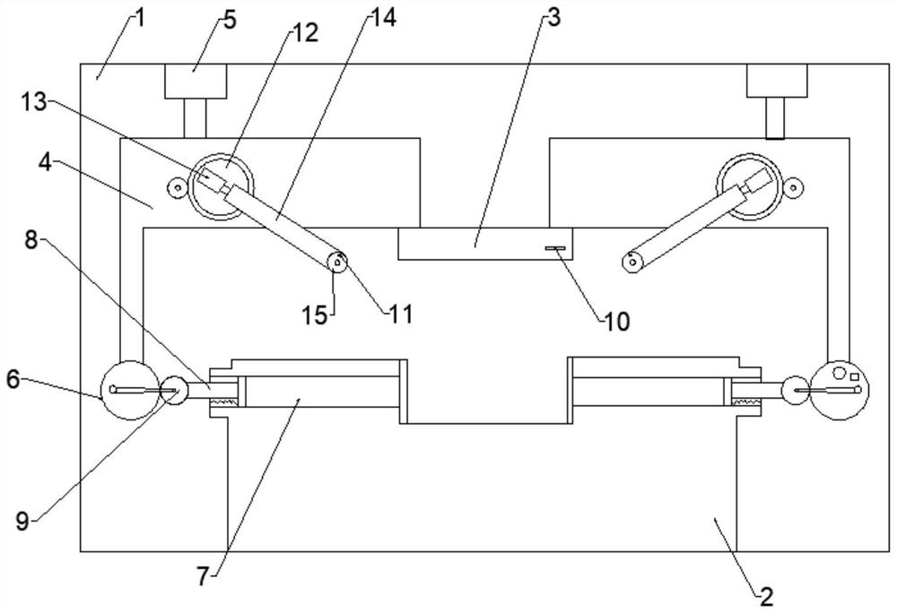
[0022] Such as figure 1 As shown, a flange positioning fixture includes a frame 1 and a control cabinet; the frame 1 is provided with a positioning plate 2, and the positioning plate 2 is provided with a positioning groove, and the frame 1 above the positioning groove is connected with a vertical Sliding ring pressure plate 3, frame 1 is provided with two pressing devices that are centered symmetrically with ring pressure plate 3; Drive the first drive...


PUM


Abstract

The invention provides a flange positioning fixture, including a frame and a control cabinet; a positioning plate is provided on the frame, a positioning groove is opened on the positioning plate, and a vertically sliding ring is connected to the frame above the positioning groove Pressing plate, the frame is provided with two pressing devices symmetrical to the center of the ring pressing plate; The first driving mechanism, the eccentric wheel installed on the lower end of the pressing frame and the negative pressure channel opened on the positioning plate; the signal of the first driving mechanism is connected to the control cabinet and fixedly connected with the pressing frame; the negative pressure channel communicates with the positioning groove; A piston is slidably connected in the negative pressure channel; the side of the piston close to the eccentric wheel rotates and installs a roller against the eccentric wheel; a connecting piece is hinged between the roller and the eccentric wheel. The invention can smoothly realize the adsorption and fixation of the flange plate, and can compress the flange plate in any direction.

Description

technical field [0001] The invention belongs to the technical field of positioning and clamping, and in particular relates to a flange plate positioning clamp. Background technique [0002] In the process of inserting the internal teeth of the existing flange plate, the flange plate moves due to the large inserting force, which leads to the phenomenon of disordered teeth. During the clamping process of the flange plate, it takes a long time to find the alignment There are many disadvantages such as affecting work efficiency, low processing quality, inconvenient installation and disassembly, and poor stability of the flange during the slotting process. [0003] In order to solve the above problems, in a flange positioning method disclosed in Chinese Patent Application No. CN201711139569.6, the compression rod pushes the piston to move out of the negative pressure channel through the roller, and a negative pressure is formed in the negative pressure channel, and the negative p...

Claims


Application Information

Patent Timeline
Patent Type & Authority Patents(China)
IPC IPC(8): B23Q3/08B23F23/06
Inventor 徐佳时
Owner 上海槎南工贸发展有限公司
Why Eureka
Try Eureka