Self-adaptive floating breathing device and breathing oil tank with same

A breathing device, self-adaptive technology, applied in the direction of valve device, oil supply tank device, engine components, etc., can solve the problem of oil leaking from the fuel tank respirator, and achieve the effect of ensuring the sealing performance

Active Publication Date: 2019-05-10
TAIYUAN INST OF CHINA COAL TECH & ENG GROUP +1
View PDF6 Cites 0 Cited by
  • Summary
  • Abstract
  • Description
  • Claims
  • Application Information

AI Technical Summary

Problems solved by technology

[0005] Aiming at the above-mentioned problems in the prior art, the present invention provides an adaptive floating breathing oil tank, which is especially suitable for large-slope roadheaders when the coal seam has a large dip angle or is affected by the geological structure. Difficulties of oil leakage from fuel tank breathers of various equipment under working conditions

Method used


Image

  • Self-adaptive floating breathing device and breathing oil tank with same
  • Self-adaptive floating breathing device and breathing oil tank with same
  • Self-adaptive floating breathing device and breathing oil tank with same

Examples


Embodiment 1

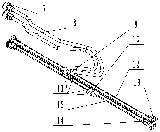
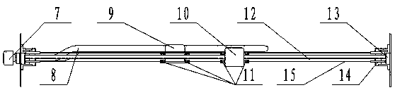
[0037] This embodiment discloses an adaptive floating breathing device, such as Figure 1-9 As shown, it includes a slidable floating breathing block 9 arranged in the fuel tank, and the floating breathing block 9 communicates with the outside through the provided breathing hose 8; when the fuel tank is tilted, the floating breathing block 9 slides to a high point to avoid Contact with oil.

[0038] A guide rod 12 is provided inside the oil tank, and the floating breathing block 9 is arranged on the guiding rod 12 and slides along the guiding rod 12; Reverse sliding power traction block 10, when the fuel tank is tilted, the power traction block 10 slides towards the low point under the action of gravity and guides the floating breathing block 9 to slide towards the high point. The fuel tank is provided with at least two guide rods 12 parallel to each other, and the floating breathing block 9 and the power traction block 10 are respectively arranged on different guide rods 12; ...

Embodiment 2

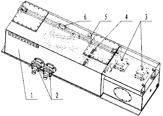
[0045] This embodiment discloses as figure 1 As shown, a breathing oil tank includes an oil tank body 1, an oil suction filter 2, an oil return filter 3, a magnetic filter 4, an oil level oil temperature gauge 5, and an adaptive floating breathing system 6. The position behind the lower right side of the oil tank body 1 is the oil suction filter 2, the position near the top of the oil tank body 1 is the oil return filter 3, the middle position in the oil tank body 1 is the magnetic filter 4, the oil tank body 1. The middle part on the left side is the oil level oil temperature gauge 5, and the top position inside the fuel tank body 1 is the self-adaptive floating breathing system 6;

[0046] Such as Figure 5 As shown, the fuel tank body 1 has the basic functions of a fuel tank and is equipped with a floating breathing system installation function. The oil drain port 16 is located at the upper right rear side of the oil tank body 1, the oil suction port 17 is located at the ...


PUM


Abstract

The invention discloses a self-adaptive floating breathing device and a breathing oil tank with the same. The breathing device comprises a slidable floating breathing block arranged in the oil tank, the floating breathing block communicates with the outside through a breathing hose arranged on the floating breathing block, and when the oil tank is inclined, the floating breathing block slides to ahigh point to be prevented from being in contact with oil liquid. According to the breathing device, the gradient change can be automatically induced, the breathing position can be automatically changed according to change of the inclination angle of the oil tank, so that the breathing position is always kept at the highest position of the oil tank. Through the action of the breathing system, theinclination angle of the oil tank is automatically induced, a power traction block slides to the lower side, at the same time, the floating breathing block is dragged to slide to the higher side along a guide rod, so that the position of a breathing opening is always at the highest position to be prevented from being submerged by the oil liquid; and the floating breathing block communicates withthe atmosphere through the breathing hose and an air filter, so that the normal breathing function of the oil tank can be met even when the inclination angle of the oil tank is large or the angle change is large.

Description

technical field [0001] The invention belongs to the technical field of coal mine machinery, and in particular relates to an adaptive floating breathing device and a breathing oil tank with the breathing device. Background technique [0002] The roadway excavation face machine excavation process usually uses a cantilever type roadheader, and the climbing ability of the roadheader is generally below 18°. When the inclination angle of the coal seam is large or the coal seam fluctuates violently due to the influence of the geological structure, due to the limitation of the climbing ability of the roadheader itself, it is impossible to continue to use the machine-dug construction roadway, which restricts the mechanized and efficient production of the coal roadway to a certain extent. This is also a problem that is difficult to solve in the process of coal production in our country. [0003] At present, many domestic scientific research institutes and mining companies have carrie...

Claims


Application Information

Patent Timeline
Patent Type & Authority Applications(China)
IPC IPC(8): F15B1/26F16K17/19
Inventor 刘子靖王焱金王学成白雪峰王帅吴晋军王瑶秦彦凯岳晓虎张立平田野贾少山马昭王传武田原王炳效王本林杨春海赵肖敏郎艳高伟杨哲勇张鑫张睿王政宏张常青毛继伟权钰云葛秦龙闫晶冀俊伟秦国强李旭江桑盛远
Owner TAIYUAN INST OF CHINA COAL TECH & ENG GROUP
Why Eureka
Try Eureka