
Touch sensor, touch module and touch sensor crack detection method

A touch sensor and touch module technology, applied in error detection/correction, instruments, static indicators, etc., can solve the problems of low precision, time-consuming and labor-intensive detection of cracks in touch sensors, etc.

Active Publication Date: 2019-05-10
BOE TECH GRP CO LTD +1
View PDF14 Cites 16 Cited by
  • Summary
  • Abstract
  • Description
  • Claims
  • Application Information

AI Technical Summary

Problems solved by technology

[0006] The purpose of the present disclosure is to provide a touch sensor, a touch module, and a touch sensor crack detection method, and then at least to a certain extent overcome the technical problems of time-consuming and labor-intensive detection of touch sensor cracks and low detection accuracy in related technologies

Method used


Image

  • Touch sensor, touch module and touch sensor crack detection method
  • Touch sensor, touch module and touch sensor crack detection method
  • Touch sensor, touch module and touch sensor crack detection method

Examples


Embodiment Construction

[0027] Example embodiments will now be described more fully with reference to the accompanying drawings. Example embodiments may, however, be embodied in many forms and should not be construed as limited to the examples set forth herein; rather, these embodiments are provided so that this disclosure will be thorough and complete, and will fully convey the concept of example embodiments to those skilled in the art. The same reference numerals in the drawings denote the same or similar structures, and thus their detailed descriptions will be omitted.

[0028] Although relative terms such as "upper" and "lower" are used in this specification to describe the relative relationship of one component of an icon to another component, these terms are used in this specification only for convenience, for example, according to the description in the accompanying drawings directions for the example described above. It will be appreciated that if the illustrated device is turned over so th...


PUM


Abstract

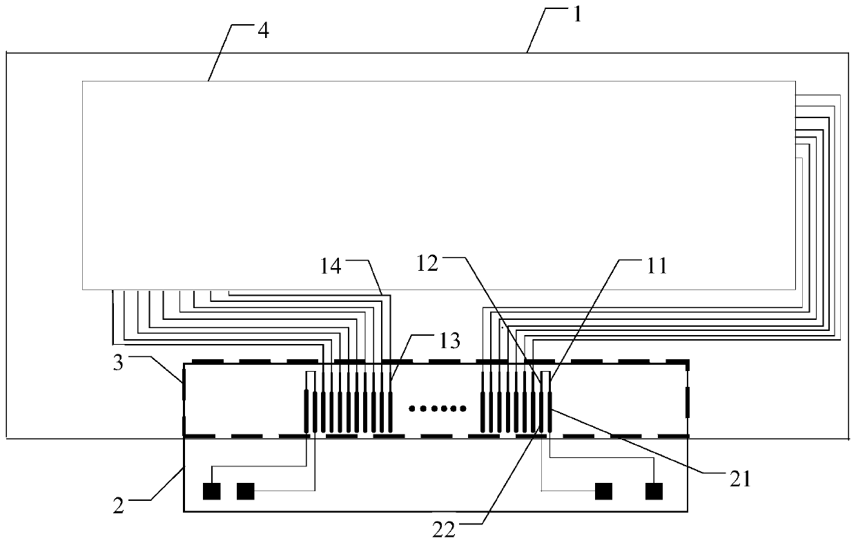
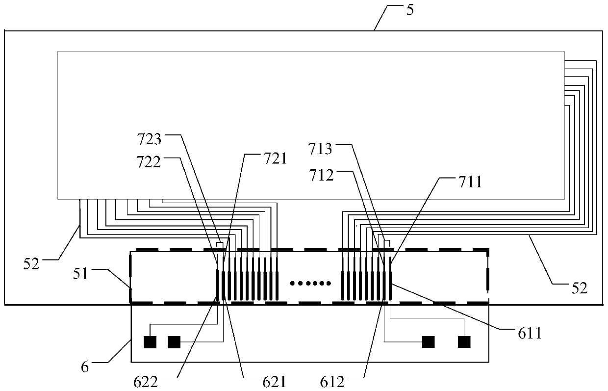
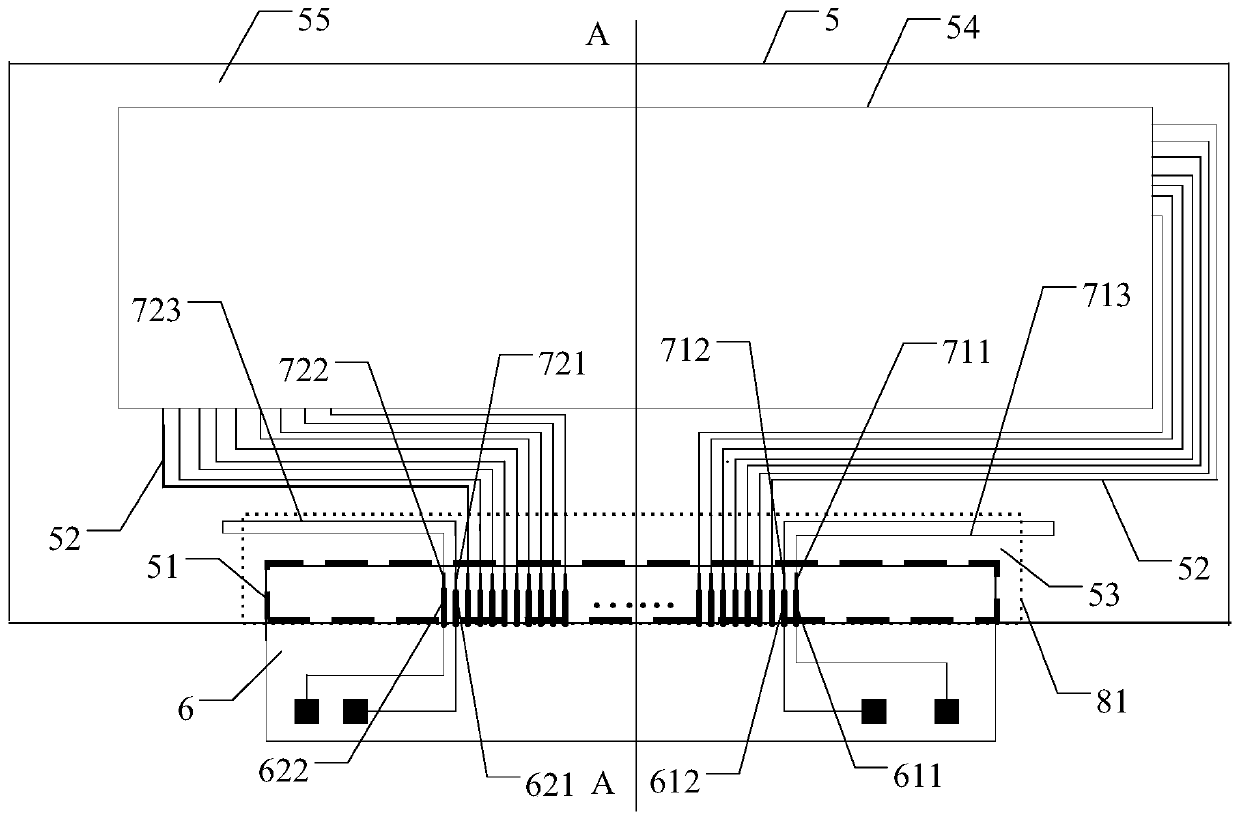
The invention relates to the technical field of display, and provides a touch sensor, the touch sensor is provided with a binding area used for binding a circuit board, and the binding area is provided with at least one test pin group used for detecting the binding state of the touch sensor and the circuit board; the test pin group comprises two test pins, the two test pins are in short circuit connection through a short circuit line, and the short circuit line extends out of the binding area. The test pin group can detect the binding state of the touch sensor and the circuit board, and can also detect whether cracks occur around the binding area of the touch sensor or not.

Description

technical field [0001] The present disclosure relates to the field of display technology, and in particular to a touch sensor, a touch module, and a crack detection method for the touch sensor. Background technique [0002] The touch module generally includes a touch sensor and a circuit board provided with a touch integrated circuit. The touch sensor is usually connected to the circuit board provided with a touch integrated circuit through a bonding technique. [0003] During the bonding process between the touch sensor and the circuit board, cracks are prone to occur around the bonding area on the touch sensor, and the cracks on the touch sensor are likely to cause problems such as breakage of the edge traces of the touch sensor, thus causing a series of problems in the touch sensor. Fault. [0004] In the related art, it is only possible to observe whether cracks appear around the bonding area of ​​the touch sensor through a microscope, and this detection method is time-...

Claims


Application Information

Patent Timeline
IPC IPC(8): G06F3/041
CPCG06F3/04164G06F2203/04103G06F11/2221G09G3/006G09G2300/0426G09G2330/12G06F3/041
Inventor 龚庆牛文骁
Owner BOE TECH GRP CO LTD
Learn More