A scanning drive mechanism
A technology of scan drive and drive mode, applied in the direction of transmission control/equalization, etc.
Active Publication Date: 2014-05-14
SHANGHAI AEROSPACE SYST ENG INST
View PDF0 Cites 1 Cited by
- Summary
- Abstract
- Description
- Claims
- Application Information
AI Technical Summary
Problems solved by technology
At present, there is no similar scanning drive mechanism in China, and there is no description or report of related technologies in similar materials at home and abroad.
Method used
View moreImage
Smart ImageViewing Examples
Examples
Embodiment Construction
Login to View More PUM
 Abstract
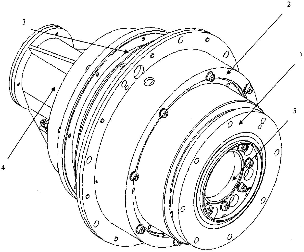
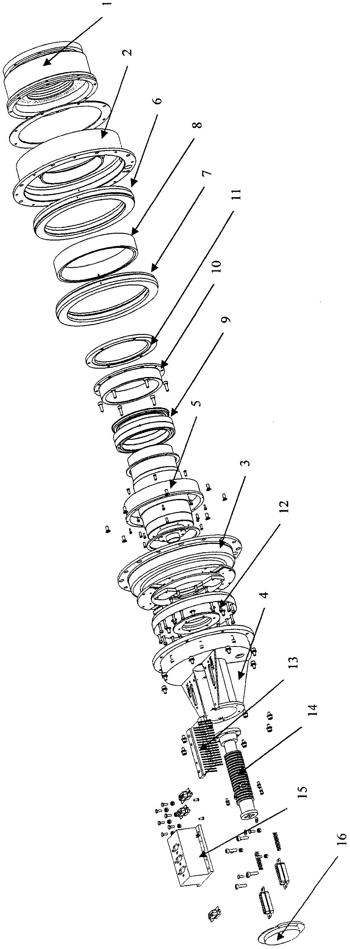
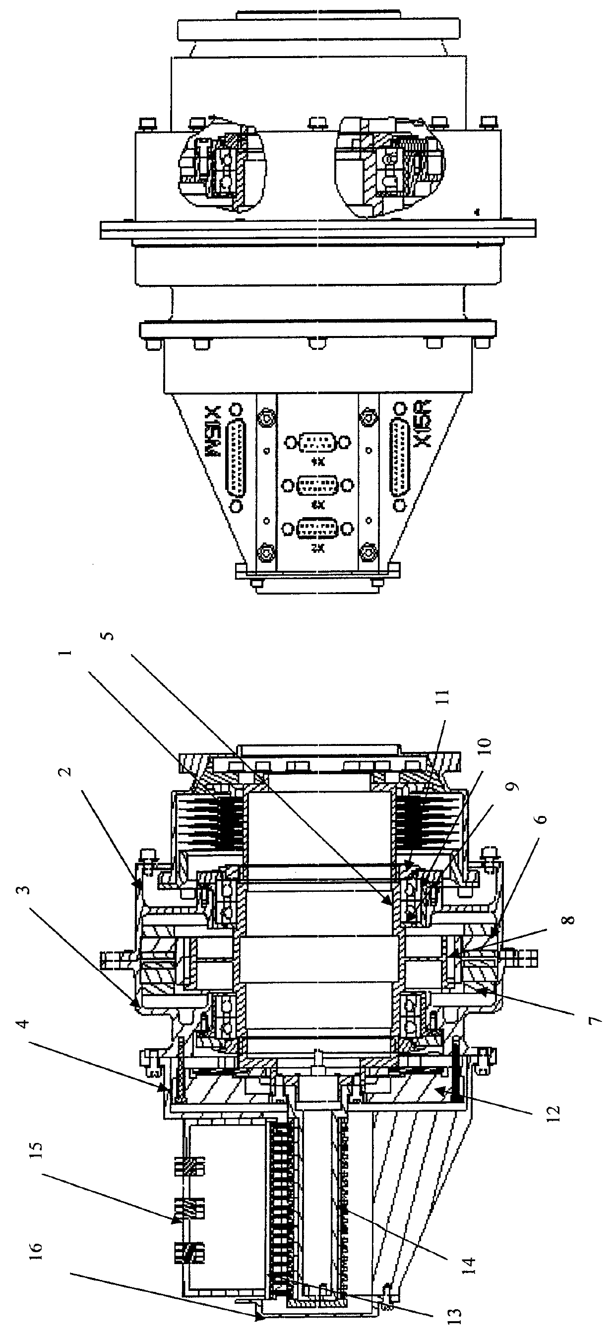
The invention proposes a scanning drive mechanism, which adopts direct drive mode and is supported by two pairs of diagonal contact ball bearings. The motor drives the rotating cylinder to rotate through the main shaft and the unloading device to realize antenna scanning. The scanning motor is a brushless DC motor, which is characterized in that it consists of an unloading device [1], an upper casing [2], a lower casing [3], a tail cover [4], a shaft [5], and a main motor stator [6] , spare motor stator[7], motor rotor[8], bearing[9], bearing bush[10], bearing lock nut[11], encoder assembly[12], slip ring fixing part[13], slip ring Ring rotating part [14], socket box [15], and tail cover end cover [16]. Since the scanning drive mechanism adopts a dual-axis output mode, one side of the output end is connected to the load through an unloading device, and the other side is connected to the slip ring Connected to achieve steady rotation, while transmitting power and signals. By adopting the invention, the beneficial effects of increasing the motor torque, reducing the motor speed and reducing the speed fluctuation are effectively obtained.
Description
technical field The invention relates to the technical field of spacecraft drive mechanisms, in particular to a steady-speed scanning drive mechanism for spacecraft antennas and other steady-speed rotational motion requirements Background technique The scanning drive mechanism is suitable for the steady-speed rotation of certain equipment of the spacecraft, such as antenna-to-ground temperature scanning and other mechanisms that require steady-speed rotation. The performance requirements for it are: stable rotation, synchronous transmission of power and signals. Most of the existing space rotation mechanisms are a one-stage deceleration method plus a slip ring method or a direct drive method. In the deceleration mode, the speed does not meet the antenna scanning requirements, and there is no synchronous transmission function under the direct drive, so the existing mechanism cannot meet the application of antenna scanning. demand. Because the scanning drive mechanism of the...
Claims
Login to View More Application Information
Patent Timeline
 IPC IPC(8): H04B7/005
Inventor 姜圣光杨金平苗军李军彪李瑞祥
Owner SHANGHAI AEROSPACE SYST ENG INST
Features
- R&D
- Intellectual Property
- Life Sciences
- Materials
- Tech Scout
- Unparalleled Data Quality
- Higher Quality Content
- 60% Fewer Hallucinations
Learn More Browse by: Latest US Patents, China's latest patents, Technical Efficacy Thesaurus, Application Domain, Technology Topic, Popular Technical Reports.
© 2025 PatSnap. All rights reserved.Legal|Privacy policy|Modern Slavery Act Transparency Statement|Sitemap|About US| Contact US: help@patsnap.com


