A Jointly Optimized Cloud Robot System Delay Optimization Method

A robot system and joint optimization technology, applied in transmission systems, manipulators, program-controlled manipulators, etc., can solve problems such as delay improvement, task execution time limit, task failure, etc., to reduce delay, reduce complexity, and improve performance. performance effect

Active Publication Date: 2021-08-13
SUN YAT SEN UNIV
View PDF0 Cites 0 Cited by
  • Summary
  • Abstract
  • Description
  • Claims
  • Application Information

AI Technical Summary

Problems solved by technology

[0006] Because of the real-time, high heterogeneity, and big data characteristics of cloud robots when performing tasks, based on real-time requirements, robots and the cloud need to perform tasks continuously, and the delay problem during task execution cannot be avoided. Task execution becomes more serious; based on the characteristics of big data, cloud robots are under pressure to process a large amount of data. If the task execution strategy cannot be well optimized, the delay will be greatly increased, and the risk of timeout will also increase accordingly.
When a task is timed out, on the one hand, it will affect the user's satisfaction due to the poor execution effect; Tasks are likely to have execution time constraints
[0007] At the same time, since the delay of the cloud robot system is affected by many factors, although there are a large number of researches on the optimization of the overall delay of the cloud robot system, the overall delay still has a lot of room for optimization.
The existing technology is mainly to adapt the scheduling algorithm in the cloud computing scene to the cloud robot system. The optimization object is the strategy of computing migration, or the selection of the transmission route in the computing migration, and the two are not organically combined. The method that leads to optimization is not efficient

Method used


Image

  • A Jointly Optimized Cloud Robot System Delay Optimization Method
  • A Jointly Optimized Cloud Robot System Delay Optimization Method
  • A Jointly Optimized Cloud Robot System Delay Optimization Method

Examples


Embodiment 1

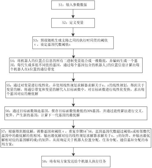
[0050] Such as figure 2 Shown, a kind of optimization method of the cloud robot system delay of joint optimization, described this optimization comprises the following steps:

[0051] S1: Input the location point information of the robot, the set is k, and input the parameters of each robot, the parameters include the robot processor frequency f max , input the computer CPU cycle required for each task, and input the calculation amount of task i Task i , input the amount of transmitted data Data generated by task i i , input the computing power E of the cloud server c 0 , input the bandwidth capability of the base station;

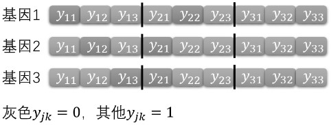
[0052] S2: Define whether the robot j is placed on the location point k to perform the task as y jk , define whether task i is assigned to robot j to execute the task as x ij , define whether the data i is uploaded to the cloud server through the base station n as z in ;

[0053] S3: Preset the threshold ε of the execution time difference between r...


PUM


Abstract

The invention discloses a method for optimizing the time delay of a cloud robot system with joint optimization. The steps of the method are as follows: input parameter data; define variables; preset the threshold ε of the execution time difference between randomly generated branches, and set the gene algebra threshold n; encode the location point information of the robot to generate a gene; each generation generates multiple sets of genes with different values, and calculates the communication bandwidth of each robot at position k through each gene; solves the linear programming about x and z, and obtains about The solution of the variable, and the communication bandwidth is substituted into the objective function, and the linear transformation is performed to find the optimal solution corresponding to each gene; the 30% genes with the lowest objective function value are screened through the objective function, and new genes are generated through the genetic algorithm; Calculate the optimal solution of the next-generation gene; adjust the gene and the threshold ε according to the above steps to find the optimal solution, output the matrix corresponding to x, y, and z of the optimal solution, and determine the layout plan; send the layout plan to a robot to perform the task .

Description

technical field [0001] The present invention relates to the technical field of service quality optimization of cloud robot clusters, and more specifically, to a joint optimization method for optimizing cloud robot system delay. Background technique [0002] At present, due to the background that traditional robots can no longer meet the production requirements well, in order to enhance the performance of individual robots, cloud robotics technology is proposed. The cloud robotics (Cloud Robotics) is a technology that applies cloud computing technology to robots. Cloud computing describes a new Internet-based IT service growth, usage and delivery model, usually involving the provision of dynamically scalable and often virtualized resources over the Internet. Using the powerful computing power and storage capacity of cloud computing to provide robots with a more intelligent "brain", this can enhance the ability of a single robot to perform complex functional tasks and services...

Claims


Application Information

Patent Timeline
Patent Type & Authority Patents(China)
IPC IPC(8): B25J9/16G06N3/12H04L29/08
Inventor 陈武辉陈晓煜郑子彬
Owner SUN YAT SEN UNIV
Why Eureka
Try Eureka