Full-automatic stacking device
A fully automatic and stacker technology, which is applied in the field of stackers, can solve the problems of increasing manpower and material resources, affecting the pace of development, and low efficiency, and achieves the effect of automatic stacking and stacking materials. The process is convenient and efficient
- Summary
- Abstract
- Description
- Claims
- Application Information
AI Technical Summary
Problems solved by technology
Method used
Image
Examples
Embodiment 1
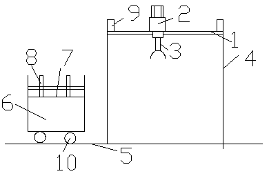
[0012] The fully automatic feeder is provided with a boom 1, the boom 1 is provided with a mobile platform 2, the lower side of the mobile platform 2 is provided with a gripping device 3, and the suspension rod 1 is provided with a moving track , the mobile platform 2 moves back and forth on the moving track, a support rod 4 is provided on the lower side of the suspension rod 1, a guide rail 5 is provided on the side of the support rod 4, and a mobile frame 6 is provided on the guide rail 5.
[0013] The moving frame 6 is provided with a storage platform 7 , and a guardrail 8 is provided on the storage platform 7 .
[0014] The two sides of the boom 1 are provided with stop rods 9 , and the stop rods 9 are located on the upper side of the boom 1 .
[0015] The lower side of the moving frame 6 is provided with a roller 10 , and the roller 10 moves on the guide rail 5 .
Embodiment 2
[0017] The fully automatic feeder is provided with a boom 1, the boom 1 is provided with a mobile platform 2, the lower side of the mobile platform 2 is provided with a gripping device 3, and the suspension rod 1 is provided with a moving track , the mobile platform 2 moves back and forth on the moving track, a support rod 4 is provided on the lower side of the suspension rod 1, a guide rail 5 is provided on the side of the support rod 4, and a mobile frame 6 is provided on the guide rail 5.
[0018] The moving frame 6 is provided with a storage platform 7 , and a guardrail 8 is provided on the storage platform 7 .
[0019] The two sides of the boom 1 are provided with stop rods 9 , and the stop rods 9 are located on the upper side of the boom 1 .
[0020] The lower side of the moving frame 6 is provided with a roller 10 , and the roller 10 moves on the guide rail 5 .
[0021] The gripping device 3 is provided with claws, and the claws are in the shape of a semi-circular arc....
Embodiment 3
[0023] The fully automatic feeder is provided with a boom 1, the boom 1 is provided with a mobile platform 2, the lower side of the mobile platform 2 is provided with a gripping device 3, and the suspension rod 1 is provided with a moving track , the mobile platform 2 moves back and forth on the moving track, a support rod 4 is provided on the lower side of the suspension rod 1, a guide rail 5 is provided on the side of the support rod 4, and a mobile frame 6 is provided on the guide rail 5.
[0024] The moving frame 6 is provided with a storage platform 7 , and a guardrail 8 is provided on the storage platform 7 .
[0025] The two sides of the boom 1 are provided with stop rods 9 , and the stop rods 9 are located on the upper side of the boom 1 .
[0026] The lower side of the moving frame 6 is provided with a roller 10 , and the roller 10 moves on the guide rail 5 .
[0027] The gripping device 3 is provided with claws, and the claws are in the shape of a semi-circular arc....
PUM
 Abstract
Description
Claims
Application Information
 - R&D
- Intellectual Property
- Life Sciences
- Materials
- Tech Scout
- Unparalleled Data Quality
- Higher Quality Content
- 60% Fewer Hallucinations
Browse by: Latest US Patents, China's latest patents, Technical Efficacy Thesaurus, Application Domain, Technology Topic, Popular Technical Reports.
© 2025 PatSnap. All rights reserved.Legal|Privacy policy|Modern Slavery Act Transparency Statement|Sitemap|About US| Contact US: help@patsnap.com

