Energy system and heater temperature adjusting control method thereof
An energy system and control method technology, applied in the energy field, can solve problems such as the inability to meet the demand for cooling and heating, and achieve the effect of reducing energy consumption and waste
Active Publication Date: 2019-05-17
QINGDAO HAIER AIR CONDITIONER GENERAL CORP LTD +1
14 Cites 1 Cited by
AI-Extracted Technical Summary
Problems solved by technology
[0003] The embodiment of the present invention provides an energy system and a control method for adjusting the heating temperature, aiming to solve the technica...
View moreAbstract
The invention discloses an energy system and a heater temperature adjusting control method thereof, and belongs to the technical field of energy sources. The energy system comprises a heat storage station, a heater and a controller, wherein the heat input end of the heat storage station is used for absorbing heat of temperature adjusting equipment capable of generating corresponding energy, and the heat output end of the heat storage station is used for releasing heat for the temperature adjusting equipment needing the corresponding energy; the heat storage station is in communication with theheater through an intermediate heat exchanger; and the controller is used for obtaining the behavior information of a user, determining the target temperature of the heater according to the behaviorinformation of the user and controlling the heater to carry out temperature adjustment based on the target temperature of the heater and the ambient temperature. The invention further provides the heater temperature adjusting control method of the energy system. According to the energy system and the heater temperature adjusting control method thereof, the heat emitted by the temperature adjusting equipment is subjected to unified scheduling, so that energy consumption and waste can be effectively reduced; and meanwhile, the heater is controlled to carry out temperature adjustment according to the behavior information of the user, so that different cold and hot requirements of the user in different states can be met.
Application Domain
Technology Topic
Heat outputIntermediate heat exchanger +7
Image
Examples
- Experimental program(1)
Example Embodiment
[0051] The following description and drawings fully illustrate specific embodiments of the present invention to enable those skilled in the art to practice them. The embodiments only represent possible changes. Unless explicitly required, individual components and functions are optional, and the sequence of operations can be changed. Parts and features of some embodiments may be included in or substituted for parts and features of other embodiments. The scope of the embodiments of the present invention includes the entire scope of the claims, and all available equivalents of the claims. In this document, each embodiment may be individually or collectively denoted by the term "invention", which is only for convenience, and if more than one invention is actually disclosed, it is not intended to automatically limit the scope of the application to any A single invention or inventive concept. In this article, relational terms such as first and second are only used to distinguish one entity or operation from another entity or operation, and do not require or imply any actual relationship or relationship between these entities or operations. order.
[0052] It should be noted that all directional indicators (such as up, down, left, right, front, back...) in the embodiments of the present invention are only used to explain the relationship between components in a particular posture (as shown in the accompanying drawings). If the relative position relationship, movement situation, etc. change, the directional indication will change accordingly. In addition, the descriptions involving "first", "second", etc. in the present invention are only for descriptive purposes, and cannot be understood as indicating or implying their relative importance or implicitly indicating the number of technical features indicated. Therefore, the features defined with "first" and "second" may explicitly or implicitly include at least one of the features.
[0053] In the description of the present invention, it should be noted that, unless otherwise clearly specified and limited, the terms "installation" and "connection" should be understood in a broad sense, for example, it can be a fixed connection, a detachable connection, or an integral The connection; it can be a mechanical connection, it can be an electrical connection; it can be a direct connection, it can be indirectly connected through an intermediate medium, or it can be a connection between two components. For those of ordinary skill in the art, the specific meanings of the above-mentioned terms in the present invention can be understood under specific circumstances.
[0054] The various embodiments herein are described in a progressive manner. Each embodiment focuses on the differences from other embodiments, and the same or similar parts between the various embodiments can be referred to each other.
[0055] In this article, such as Figure 13 to Figure 17 As shown, the energy storage station 10 and the energy absorption end 101 of the energy storage station 10 are used to absorb energy from a temperature adjustment device (absorption end temperature adjustment device 1011) that can generate corresponding energy, and the energy release end 102 is used to send energy to those that need corresponding energy. The temperature adjustment device (release end temperature adjustment device 1021) releases energy.
[0056] The specific form of the energy storage station 10 is not limited, and its main function is to store energy, and it contains energy storage materials capable of storing energy, and the energy storage station 10 can be insulated and kept warm. The energy storage station 10 can be a heat-insulating box filled with energy storage materials. It can also be a storage pool dug on the ground, and the inner wall of the storage pool is thermally insulated. In the energy storage station 10, the stored energy can be divided into heat and cold according to the temperature reflected by the energy. Therefore, the heat and cold are relative concepts, which are divided according to the set limit (eg, temperature limit). can. Therefore, herein, the energy storage station 10 may be a heat storage device 11 (heat storage station 11) or a cold energy storage device 12 (cold energy storage station 12).
[0057] The energy absorbing end 101 of the heat storage device 11 is the heat absorbing end 111, which is used to absorb the heat of the first temperature regulating device 1111 that can generate heat, and the energy releasing end 102 is the heat releasing end 112, which is used to send heat to the The second temperature adjusting device 1121 releases heat. For example, the first temperature adjustment device may be a refrigerator, an outdoor unit of an air conditioner during cooling of an air conditioner, an air energy compressor, a solar heat collection and temperature adjustment device, a mobile robot heat release charger, and the like. The second temperature regulating device may be a water heater, heating air conditioner, heating temperature regulating device, heating device, etc.
[0058] The energy absorption end 101 of the cold energy storage device 12 is the cold energy absorption end 121 (that is, the heat release end) for absorbing the cold energy of the third temperature regulating device 1211 that can generate cold energy, and the energy release end 102 is the cold energy The release end 122 (that is, the heat absorption end) is used to release cold energy to the fourth temperature regulating device 1221 that requires cold energy. For example, the third temperature adjustment device may be an outdoor unit of an air conditioner, a compressor, a cold collection and temperature adjustment device, etc. during heating. The fourth temperature adjustment device may be a refrigerator, a freezer, a refrigeration air conditioner, and the like.
[0059] In this article, the following energy storage station 10 can refer to the heat storage station 11 or the cold energy storage station 12 without special instructions. The energy absorption end can be the heat absorption end or the cold energy absorption end. The energy releasing end can be the heat releasing end or the cold releasing end.
[0060] In this article, temperature control equipment refers to equipment that can change the temperature of itself or the environment when the equipment is working, such as refrigerators, air conditioners, air compressors, solar heat collection and temperature control equipment, and mobile robot heat release chargers. , Water heaters, heating and temperature regulating equipment, heating devices, compressors, cold collection and temperature regulating equipment, freezers.
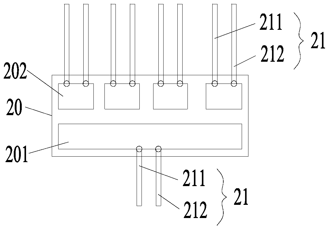
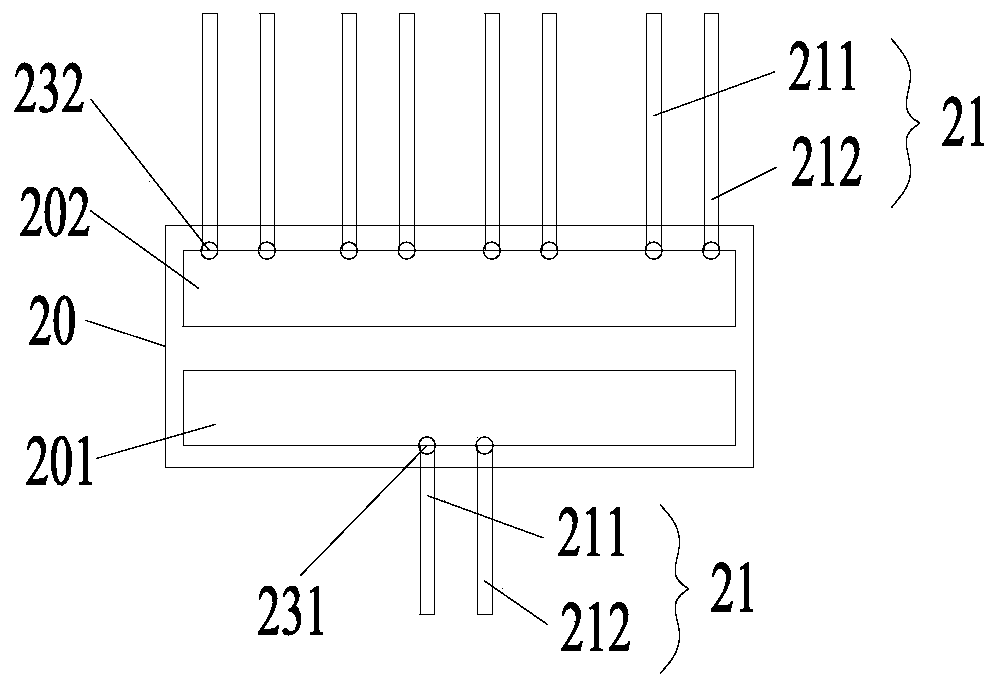
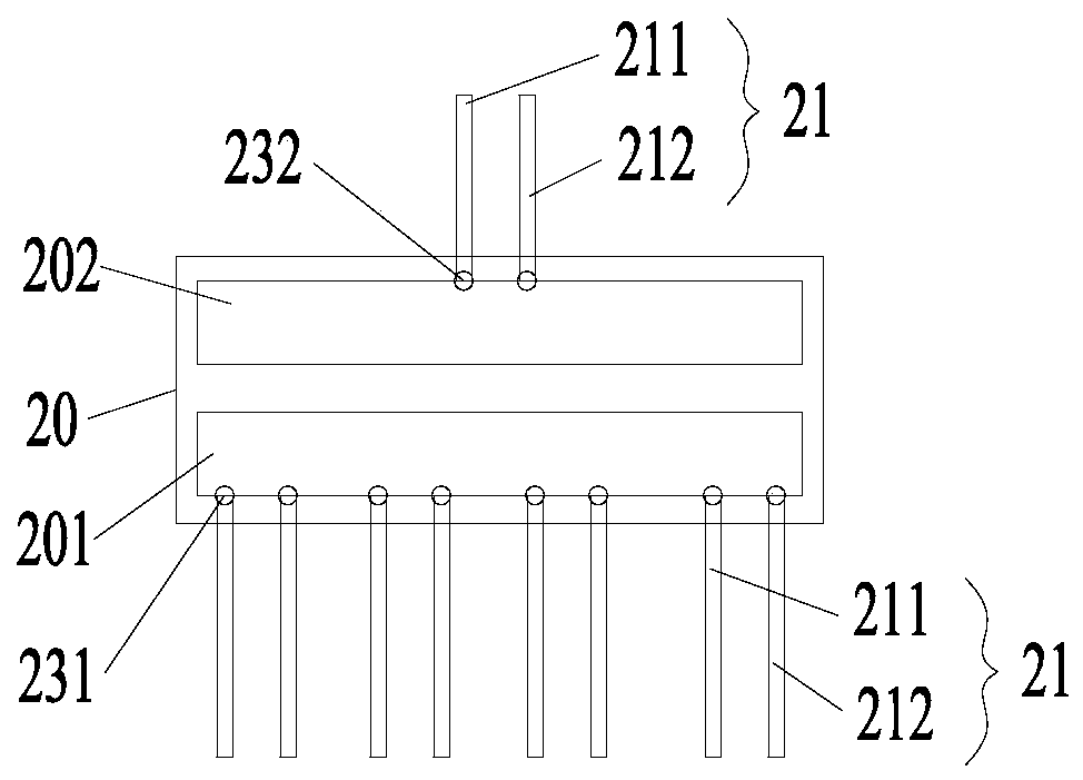
[0061] Combine Figure 1 to Figure 6 As shown, illustrating the first aspect of the embodiment of the present invention, an intermediate heat exchanger, denoted as the first intermediate heat exchanger 20, includes:
[0062] The heat-absorbing end 201 is used to connect to the energy storage station 10/temperature regulating device (for example, the first temperature regulating device 1111 or the fourth temperature regulating device 1221); and,
[0063] The radiating end 202 is used to connect to a temperature adjustment device (for example, the second temperature adjustment device 1121 or the third temperature adjustment device 1211)/energy storage station 10.
[0064] The first intermediate conversion heat exchanger 20 of the embodiment of the present invention is connected between the energy storage station 10 and the temperature regulating device, and plays a role in the transfer of energy between the energy storage station 10 and a plurality of temperature regulating devices. In practical applications, the number of temperature adjustment devices is variable, and it can be one, two, or even more; and the energy storage station 10 can also have one or more. Therefore, in the embodiment of the present invention, the conversion heat There are one or more heat-absorbing ends 201 and one or more heat-dissipating ends 202 of the device, which can realize multi-channel conversion, multi-channel conversion, or multi-channel conversion, which can facilitate the adjustment of the energy storage station 10 and the adjustment The energy storage and release between the temperature devices (the absorption end temperature adjustment device 1011 or the release end temperature adjustment device 1021), and the passage control is convenient. According to the actual situation, some of the passages can be connected for energy exchange. Moreover, the communication pipeline between the energy storage station and the temperature control equipment can be simplified, the pipeline layout is convenient, and the cost is reduced.
[0065] In the intermediate conversion heat exchanger 20 of the embodiment of the present invention, when the heat absorption end 201 is connected to the energy storage station 10, the heat release end 202 is connected to the temperature adjustment equipment, and the energy storage station 10 supplies heat to the temperature adjustment equipment through the intermediate conversion heat exchanger 20 It may also be that the temperature regulating device supplies cold energy to the energy storage station through the intermediate heat exchanger 20. When the heat-absorbing end 201 is connected to the temperature regulating device, the heat-emitting end 202 is connected to the energy storage station 10, and the temperature regulating device supplies heat to the energy storage station 10. Alternatively, the energy storage station 10 supplies cold energy to the temperature regulating device.
[0066] In the embodiment of the present invention, the heat-absorbing end 201 is used to absorb the heat of the energy storage station 10 (or the first temperature adjustment device 1111), that is, the end of cooling capacity (releasing cooling capacity). Various specific structures are used. For example, the fluid medium is used as the carrier, and the heat-absorbing end 201 adopts a heat exchange device and the heat-exchanging device of the heat releasing end 112 (or the first temperature regulating device 1111) on the side of the heat storage station 11 passes through the pipeline. Connected, the fluid medium absorbs heat from the heat storage station 11 side (or the first temperature regulating device 1111), the fluid medium flows to the heat absorption end 201, and the heat absorption end 201 exchanges heat with the medium fluid at the heat release end 202, thereby The heat is transferred to the exothermic end 202. Alternatively, the heat-absorbing end 201 adopts a heat exchange device to communicate with the heat exchange device of the cold-capacity absorption end 121 (or the fourth temperature adjustment device 1221) of the cold-capacity storage station 12 through a pipeline. At this time, the heat-absorption end 201 can understand In order to release the cold end 201, the fluid medium absorbs heat from the side of the cold storage station 12 (or the fourth temperature regulating device 1221) (absorbs heat, that is, releases cold), and the fluid medium flows to the end 201 to absorb heat The end 201 exchanges heat with the medium fluid of the heat-emitting end 202 to transfer heat to the heat-emitting end 202.
[0067] In the same way, the heat release end 202 is used to release heat to the energy storage station 10 (or the second temperature adjustment device 1121), that is, the absorption cold end (absorb cold energy). Various specific structures are adopted. For example, the fluid medium is used as the carrier, and the heat-exchanging device at the heat-releasing end 202 is used with the heat-exchanging device of the heat-absorbing end 111 (or the second temperature regulating device 1121) on the side of the heat storage station 11 through the pipeline Connected, the fluid medium absorbs heat from the heat storage station 11 side (or the second temperature regulating device 1121), the fluid medium flows to the heat release end 202, and the heat release end 202 exchanges heat with the medium fluid at the heat absorption end 201, thereby The heat is transferred to the heat sink 201. Alternatively, the heat release end 202 is connected with the heat exchange device of the cold discharge end 122 (or the third temperature adjustment device 1211) of the cold storage station 12 by a heat exchange device through a pipeline, and the fluid medium is directed to the cold storage station 12 side (Alternatively, the third temperature adjustment device 1211) releases heat (releases heat, that is, absorbs cold energy), the fluid medium flows to the exothermic end 202, and the medium fluid between the exothermic end 202 and the heat absorption end 201 exchanges heat, thereby The heat is transferred to the heat sink 201.
[0068] That is, when the intermediate heat exchanger is applied to the cold energy storage device, the reverse process of heat transfer in the intermediate heat exchanger 20 is cold energy transfer, that is, heat is absorbed and cold energy is released.
[0069] In an alternative embodiment, the heat-absorbing end 201 specifically adopts a heat exchange device, such as a plate heat exchanger, an evaporator, or a heat exchange coil. The heat release end 202 specifically adopts a heat exchange device, such as a plate heat exchanger, a condenser, or a heat exchange coil.
[0070] In the first intermediate heat exchanger 20 of the embodiment of the present invention, the number of the heat-absorbing end 201 and the heat-releasing end 202, and the arrangement of the external connecting pipe group of the heat-absorbing end 201 and the heat-releasing end 202 are based on the connecting side The number of connecting pipe groups of the heat exchange device (the energy storage station side and the temperature control equipment side) (see the energy storage station part below) can be determined.
[0071] In an alternative embodiment, there are one or more heat-absorbing ends 201 of the first heat conversion device 20 in the embodiment of the present invention, and the pipes of each heat-absorbing end 201 are independently arranged. For example, the heat sink 201 includes one (such as figure 1 , figure 2 with Image 6 Shown) or more (see Figure 4 The heat-releasing end 202 of the intermediate heat exchanger 20) the third heat exchange device, each third heat exchange device has a liquid inlet pipe 211 and a liquid outlet pipe 212 (ie, a set of connecting pipe groups 21), which pass through two Two pipelines are connected to the heat exchange device on the side of the energy storage station 10 (or the first temperature regulating device 1111 or the fourth temperature regulating device 1221), and the energy storage station 10 (or the first temperature regulating device 1111 or The heat on the side of the fourth temperature regulating device 1221) is transferred to the heat absorbing end 201. That is, each third heat exchange device independently communicates with the energy storage station 10 (or the first temperature regulating device 1111 or the fourth temperature regulating device 1221). Another example, such as image 3 , Figure 5 As shown, the heat absorption end 201 is a third heat exchange device, and the liquid inlet end of the third heat exchange device is connected with a plurality of liquid inlet pipes 211, and the liquid outlet end is connected with a plurality of liquid pipes 212. A liquid inlet pipe 211 and a liquid outlet pipe 222 are used as a connecting pipeline group 21 to form a plurality of independent connecting pipeline groups, through which the plurality of independent connecting pipeline groups are respectively exchanged with the third heat exchange on the side of the external temperature regulating device The device is connected.
[0072] In another alternative embodiment, there are multiple heat-absorbing ends 201, and the pipes of the multiple heat-absorbing ends 201 communicate with each other. There are many ways to communicate with each other, as long as multiple heat absorption ends can be connected to the energy storage station 10 (or the first temperature regulating device 1111 or the fourth temperature regulating device 1221). For example, such as Figure 4 As shown, a plurality of heat absorption ends 201 are communicated with a liquid inlet transfer pipe 221 and a liquid outlet transfer pipe 222. The liquid inlet pipe 211 of each heat absorption end 201 is connected with the liquid inlet transfer pipe 221, and each heat sink The liquid outlet pipe 212 of the end 201 is in communication with the liquid outlet transfer pipeline 222. Then pass the inlet transfer pipeline 221 and the outlet transfer pipeline 222 as a set of connected pipeline groups, and pass through two pipelines with the energy storage station 10 (or the first temperature regulating device 1111 or the fourth temperature regulating device 1221) The heat exchange device on the side is connected.
[0073] In the same way, when there are one or more radiating ends 202, the pipes of each radiating end 202 are independently arranged, and the setting method is the same as the aforementioned heat absorbing end 201. When there are multiple radiating ends 202, the pipes of the multiple radiating ends 202 are connected to each other, and the connection mode is the same as the aforementioned heat absorbing end 201. I will not repeat them here.
[0074] Therefore, in the first heat exchanger of the embodiment of the present invention, there are the following specific embodiments according to the arrangement of the pipes of the heat absorption end 201 and the heat exchange end 202.
[0075] Such as figure 1 As shown, in the first intermediate heat exchanger I, there is one heat-absorbing end 201 with one connecting pipe group; there are multiple heat-releasing ends 202, and the connecting pipe groups of the multiple heat-releasing ends 202 are independently arranged. That is, the pipes of the heat absorption end 201 and the heat release end 202 are independently provided. Turn all the way to multiple ways.
[0076] Such as figure 2 As shown, in the first intermediate heat exchanger II, there is one heat-absorbing end 201 with one connecting pipe group; one heat-releasing end 202 has one heat-releasing end 202 with multiple independently arranged connecting pipe groups. That is, the pipes of the heat absorbing end 201 and the heat radiating end 202 are provided independently. Turn all the way to many ways.
[0077] Such as image 3 As shown, in the first intermediate heat exchanger III, there is one heat-absorbing end 201, and one heat-absorbing end 201 has a plurality of independently arranged connecting pipe groups; the heat releasing end 202 is one with one connecting pipe group. That is, the pipes of the heat absorbing end 201 and the heat radiating end 202 are provided independently. Multi-way transfer.
[0078] Such as Figure 4 As shown, in the first intermediate heat exchanger V, there are multiple heat-absorbing ends 201, and the multiple heat-absorbing ends 201 are connected to each other by a set of connecting pipe groups and the energy storage station 10 (or the absorption end temperature regulating device 1011). The heat device is connected; there are multiple heat releasing ends 202, and the connecting pipe groups of the multiple heat releasing ends 202 are independently arranged. That is, the pipes of the plurality of heat absorbing ends 201 communicate with each other, and the pipes of the plurality of heat releasing ends 202 are independently arranged. Turn all the way to many ways.
[0079] Such as Figure 5 As shown, in the first intermediate heat exchanger IV, there is one heat-absorbing end 201, and one heat-absorbing end 201 has a plurality of independently arranged connecting pipe groups; there is one heat-emitting end 202, and one heat-emitting end 202 has multiple independent Set the connected pipeline group. That is, the pipes of the heat absorbing end 201 and the heat radiating end 202 are provided independently. Multi-channel to multi-channel.
[0080] Such as Image 6 As shown, in the first middle heat exchanger VI, there is one heat-absorbing end 201 with one connecting pipe group; and one heat-releasing end 202 has one connecting pipe group. That is, the pipes of the heat absorption end 201 and the heat release end 202 are independently provided. Turn all the way.
[0081] Of course, the structure of the first heat exchanger in the embodiment of the present invention is not limited to the above six types, and the structures of the heat absorption end 201 and the heat release end 202 can be interchanged or combined arbitrarily. The number of connecting pipe groups of the heat exchange device on the connecting side (the energy storage station side and the temperature regulating equipment side) determines the structure of the suitable intermediate heat exchanger. In addition, when the connecting pipe groups of the heat-absorbing end 201 (or the heat-releasing end 202) of the first heat exchanger are multiple groups, the number is not limited, and depends on the energy storage station 10 or the temperature control equipment to be connected. The number can be determined.
[0082] In the first intermediate heat exchanger 20 of the embodiment of the present invention, the heat exchange device of the heat-absorbing end 201 and the heat exchange device of the heat-emitting end 202 can be arranged separately, for example, when a plate heat exchanger is used, the two are arranged oppositely (can be Contact or non-contact) to ensure the maximum heat exchange area; when heat exchange coils are used, the coils of the two are arranged alternately (contact or non-contact) to ensure effective heat exchange. Alternatively, the heat exchange device of the heat absorption end 201 and the heat exchange device of the heat release end 202 are designed as a whole. The arrangement method is not limited, as long as it is realized that the heat exchange device at the heat absorption end 201 and the heat exchange device at the heat release end 202 can perform heat transfer. Such as Figure 1 to Figure 6 As shown, both the heat-absorbing end 201 and the heat-dissipating end 202 adopt a non-contact heat exchange device structure. Of course, the first heat exchanger of the embodiment of the present invention is not limited to the structure given in the drawings.
[0083] In an alternative embodiment, the intermediate heat exchanger 20 further includes a heat absorption valve 231 arranged in series on the pipeline of the heat absorption end 201; and/or a heat release valve 232 arranged in series on the heat emission end 202 on the pipeline. The purpose of setting the valve is to control the opening or closing of the heat absorption end 201 and the heat release end 202. In specific embodiments, a heat absorption valve 231 is provided on the liquid inlet pipe and the liquid outlet pipe of each heat absorption end 201 (each heat exchange device), and each heat release end 202 (one heat exchange device) Both the liquid inlet pipe and the liquid outlet pipe are provided with a heat release valve 232. Through the control of the valves, the opening and closing control of the communicating pipes of the heat release end 202 and the heat absorption end 201 of the centering conversion heat exchanger 20 are realized respectively, and the energy transmission can be adjusted. The energy storage station 10 can be controlled according to actual conditions. To release energy to part of the temperature regulating equipment, it is also possible to control part of the temperature regulating equipment box energy storage station 10 to store energy.
[0084] Combine Figure 7 with Figure 8 As shown, in the embodiment of the present invention, there is also provided an intermediate heat exchanger, and the second intermediate heat exchanger 30 includes:
[0085] The heat-absorbing end 301 is used to connect to the energy storage station 10/temperature regulating device (for example, the first temperature regulating device 1111 or the fourth temperature regulating device 1221);
[0086] The radiating end 302 is used to connect to the temperature adjustment device (for example, the second temperature adjustment device 1121 or the third temperature adjustment device 1211)/energy storage station 10; and,
[0087] The unidirectional heat conducting device 31, the heat absorbing end 301 and the heat releasing end 302 are arranged at both ends of the unidirectional heat conducting device 31.
[0088] The second intermediate heat transfer device 30 of the embodiment of the present invention can provide precise energy for the temperature control equipment when the energy storage station releases energy to the discharge end temperature control equipment by adding a one-way heat conducting device 31. In addition, it is also applicable to situations where energy transmission between the energy storage station 10 and the temperature adjustment device (the absorption end temperature adjustment device 1011 or the discharge end temperature adjustment device 1021) cannot be carried out in a set direction. Generally, when heat is transferred, it can only be transferred from the high temperature end to the low temperature end. If the temperature in the heat storage station is higher than the temperature of the medium output by the temperature regulating device, at this time, the heat storage station still has a lot of heat supply The storage capacity, at this time, the heat storage station cannot be stored in the set direction, but it will cause the heat loss of the heat storage station, which has the opposite effect. The same problem is encountered when the heat storage station releases heat. Therefore, the embodiment of the present invention provides the second intermediate heat transfer device 30, which uses the unidirectional heat guide device 31 to guide the medium temperature of the heat (cold capacity) storage station from the temperature regulating device, and guide the equipment from the heat (cold capacity) storage station The temperature of the medium is adjusted so that it can provide accurate energy to the temperature regulating device at the release end, or the energy storage station 10 and the temperature regulating device can transfer heat normally in the set direction.
[0089] The second intermediate heat transfer device 30 of the embodiment of the present invention is based on the aforementioned first intermediate heat transfer device 20, and a single heat conduction device 31 is added between the heat absorption end and the heat release end. Therefore, the structure of the absorption end 301 and the heat release end 302 of the second middle heat exchanger 30 and their functions are the same as those of the heat absorption end 201 and the heat release end 202 of the first middle heat exchanger 20. The foregoing content will not be repeated here.
[0090] Therefore, based on Figure 1 to Figure 6 In the structure of the first intermediate heat transfer device I to the first intermediate heat transfer device VI, the one-way heat conducting device 31 is added between the heat absorption end and the heat release end, and then the heat absorption end and the heat release end corresponding to the same The second intermediate heat exchanger I to the second intermediate heat exchanger VI. Such as Figure 7 The second intermediate heat exchanger II 30 shown is obtained by adding a one-way heat transfer device 31 on the basis of the first intermediate heat exchanger II 20, such as Figure 8 The second intermediate heat exchanger VI30 shown is obtained by adding a one-way heat transfer device 31 to the first intermediate heat exchanger VI20.
[0091] In the second intermediate heat transfer unit 30 of the embodiment of the present invention, the unidirectional heat conducting device 31 realizes (forced) exchange of heat from the heat-absorbing end to the heat-emitting end. Specifically, a refrigerant heat exchanger or a semiconductor temperature regulator can be used.
[0092] In an alternative embodiment, the refrigerant heat exchanger includes an evaporator 311, a compressor (not shown), a condenser 312, and an expansion valve (not shown), which are connected to form a heat exchange circuit. The second middle heat transfer device 30 includes two heat absorption chambers 303 and a heat release chamber 304 that are arranged for heat insulation and heat preservation; the evaporator 311 is arranged opposite to the heat absorption end 301 of the second middle heat transfer device 30 and is arranged at the heat sink In the chamber 303; the condenser 312 is arranged opposite to the heat release end 302 of the second middle heat exchanger 30, and is arranged in the heat release chamber 304.
[0093] In another alternative embodiment, the semiconductor temperature regulator includes a semiconductor refrigeration fin, a first end heat exchanger arranged on the first end of the pelvis and a second end heat exchanger at the second end, and a power supply Device. The power supply device is used to provide electrical energy for the semiconductor refrigeration sheet. By controlling the direction of the power supply current, the first end and the second end of the peltier can be switched in two modes of heat generation and cold generation. For example, under forward current, the first end is the cold end and the second end is the hot end; after switching the current direction, the first end is switched to the hot end and the second end is switched to the cold end. The second middle heat exchanger 30 includes two heat-absorbing chambers 303 and a heat-releasing chamber 304 arranged with adiabatic heat preservation; the first end heat exchanger is arranged opposite to the heat-absorbing end 301 of the second middle heat exchanger 30 and arranged In the heat absorption chamber 303; the second end heat exchanger is arranged opposite to the heat release end 302 of the second middle heat exchanger 30, and is arranged in the heat release chamber 304. According to the actual situation, it is sufficient to determine the first end heat exchanger as the hot end (or cold end) and the second end heat exchanger as the cold end (or hot end).
[0094] When it is necessary to provide accurate energy to the temperature regulating device at the release end, or when the heat transfer between the energy storage station 10 and the temperature regulating device cannot be carried out in the set direction, the unidirectional heat conducting device 31 is activated to reduce the heat of the heat sink 301 It is forced to exchange to the heat release end 302, and then the heat release end 302 transfers the heat to the energy storage station 10 (or the absorption end temperature adjustment device 1011, or the release end temperature adjustment device 1021).
[0095] Combine Figure 9 to Figure 12 , In a second aspect of the embodiments of the present invention, an energy system includes:
[0096] The energy storage station 10, the energy absorption end 101 of the energy storage station 10 is used to absorb the energy of the temperature adjustment device (absorption end temperature adjustment device 1011) that can generate corresponding energy, and the energy release end 102 is used to send the corresponding energy to the temperature adjustment device (Release end temperature regulating device 1021) Release energy. as well as,
[0097] One or more of the aforementioned first intermediate heat exchanger 20, and/or, one or more of the aforementioned second intermediate heat exchanger 30, in the energy storage station 10 and the temperature regulating device (absorption end temperature regulating device 1011 or release The first intermediate heat exchanger 20 and/or the second intermediate heat exchanger 30 are connected between the end temperature regulating devices 1021).
[0098] In an alternative embodiment, when the first intermediate conversion heat exchanger 20 and the second intermediate conversion are connected between the energy storage station 10 and the temperature adjustment device (the absorption end temperature adjustment device 1011 or the release end temperature adjustment device 1021) When the heat exchanger 30 is used, the first intermediate heat exchanger 20 and the second intermediate heat exchanger 30 have a one-to-one correspondence, and the second intermediate heat exchanger 20 is connected in parallel between the first intermediate heat exchanger 20 and the energy storage station 10 On line 24.
[0099] That is, the energy system of the embodiment of the present invention has the following specific embodiments.
[0100] Such as Picture 9 As shown, the first type of energy system includes an energy storage station 10 and a first intermediate heat exchanger 20. The energy storage station 10 and the temperature adjustment device (the absorption end temperature adjustment device 1011 or the release end temperature adjustment device 1021) are connected to the first One heat converter 20. In the first energy system, in addition to adopting Picture 9 In addition to the first heat exchanger II shown, you can also use figure 1 , image 3 with Figure 4 The first heat conversion device shown realizes the one-to-multiple connection of the energy storage station 10 and multiple temperature control devices. You can also use such as Figure 5 The shown multiple-to-multiplex first intermediate heat exchanger V is suitable for multiple connections of the heat-absorbing end 201 (or the heat-emitting end 202) of the first intermediate heat exchanger when there are multiple energy storage stations 10 The pipelines are respectively connected with multiple energy storage stations 10 to realize that multiple energy storage stations 10 release energy to the temperature regulation device at the same time, or multiple temperature regulation devices can simultaneously store energy to multiple energy storage stations 10.
[0101] Such as Picture 10 As shown, the second type of energy system includes an energy storage station 10 and a second intermediate heat exchanger 30. The energy storage station 10 and the temperature adjustment device (the absorption end temperature adjustment device 1011 or the release end temperature adjustment device 1021) are connected to the first The second heat exchanger 30. In this second energy system, in addition to adopting Picture 10 The second intermediate heat exchanger shown II ( Figure 7 In addition to (shown), the second intermediate heat exchanger I, the second intermediate heat exchanger III, and the second intermediate heat exchanger IV can also be used to realize the one-to-multiple connection of the energy storage station 10 and multiple temperature regulating devices . It is also possible to use a multiple-to-multiplex second intermediate heat exchanger V, which is suitable for multiple connections of the heat absorption end 201 (or the heat release end 202) of the first intermediate heat exchanger when there are multiple energy storage stations 10 The pipelines are respectively connected with multiple energy storage stations 10 to realize that multiple energy storage stations 10 release energy to the temperature regulation device at the same time, or multiple temperature regulation devices can simultaneously store energy to multiple energy storage stations 10.
[0102] The third type of energy system includes an energy storage station 10, a first intermediate heat exchanger 20 and a second intermediate heat exchanger 30, the energy storage station 10 and part of the temperature adjustment equipment (the absorption end temperature adjustment device 1011 or the release end temperature adjustment device 1021) is connected to the first intermediate heat transfer device 20, and the second intermediate heat transfer device 30 is connected to another part of the temperature control equipment.
[0103] Such as Picture 11 As shown, the fourth type of energy system includes an energy storage station 10, a first intermediate heat exchanger 20, and a second intermediate heat exchanger 30, and the first intermediate heat exchanger 20 and the second intermediate heat exchanger 30 have a one-to-one correspondence. , The first intermediate conversion heat exchanger 20 is connected between the energy storage station 10 and the temperature adjustment device (absorption end temperature adjustment device 1011 or release end temperature adjustment device 1021), and the second intermediate conversion heat exchanger 30 is connected in parallel to the first intermediate conversion On the connecting pipeline between the heat exchanger and the energy storage station 10. In this fourth energy system, in addition to the first intermediate heat exchanger II and the second intermediate heat exchanger VI, the other five first intermediate heat exchangers and the second intermediate heat exchanger can be used. The number of energy storage stations 10 during application, the number of temperature regulating devices and other factors can be set and arranged.
[0104] The first to fourth energy systems mentioned above are not limited to Figure 9 to Figure 11 The first intermediate heat exchanger 20 and the second intermediate heat exchanger 30 used in, according to the structure of the energy absorbing end 101 and the energy releasing end 102 of the energy storage station 10, as well as the number of temperature regulating equipment, etc. The heat-receiving end and the heat-releasing end of the intermediate heat exchanger can be used.
[0105] For the fourth type of energy system, it also includes a switching device. The switching device is arranged at the connection interface of the second middle heat exchanger 30 and the connecting pipe 24 connected in parallel, for switching between the energy storage station 10 and the temperature regulating device. The first intermediate heat transfer device is connected or communicated through the second intermediate heat transfer device. Specifically, the switching device is a control valve group, which includes two valves, an inlet control valve 161 and a return control valve 161. The first state and the sealing of the parallel pipeline of the heat exchanger 30 are converted in the second block. The switching between the second state of the blocked connecting pipeline 24 realizes the communication between the energy storage station 10 and the temperature regulating device through the first intermediate heat exchanger or the second intermediate heat exchanger.
[0106] In a further optional embodiment, it further includes a control device. The output end of the control device is connected to the control end of the switching device; when it is determined that the energy storage station 10 and the temperature adjustment device (the absorption end temperature adjustment device 1011 or the release end adjustment device) When the temperature equipment 1021) cannot perform heat exchange in the set direction, the switching device is controlled to switch the energy storage station 10 and the temperature adjustment equipment to communicate through the second intermediate heat exchanger 30.
[0107] Specifically, by detecting the first medium temperature on the side of the energy storage station 10 and the second medium temperature on the side of the temperature regulating device, and by judging the relationship between the first medium temperature and the second medium temperature, the energy storage station 10 and the temperature regulating device ( Whether the absorption end temperature adjustment device 1011 or the release end temperature adjustment device 1021) can exchange heat in a set direction. For example, the energy storage station 10 is the heat storage station 11, and the release end temperature adjustment device 1201 is the second temperature adjustment device 1121, and the first middle conversion heat exchanger II 20 is connected between the heat storage station 11 and the plurality of second temperature adjustment devices 1121 (Such as figure 2 Shown), and connect the second intermediate heat exchanger II 30 in parallel to the connecting pipeline between the first intermediate heat exchanger II 20 and the heat storage station 11. The set heat exchange direction is that the heat storage station 11 supplies heat to the plurality of second temperature adjustment devices 1121. The prerequisite for achieving the set heat exchange direction is that the temperature of the first medium on the side of the heat storage station 11 is greater than the second temperature adjustment device. The second medium temperature on the device side. Therefore, when the temperature of the first medium is lower than the temperature of the second medium, the heat storage station 11 and the plurality of second temperature adjustment devices 1121 cannot perform heat exchange in the set direction. At this time, control the switching device to switch the heat storage The station 11 is in communication with the second temperature regulating device 1121 through the second intermediate heat exchanger II30. By analogy, the switching control principle between the heat storage station 11 and the plurality of first temperature adjustment devices 1111 (absorption end temperature adjustment devices) is the same, and will not be repeated here.
[0108] In the energy system of the embodiment of the present invention, the intermediate heat exchanger (the first intermediate heat exchanger and/or the first intermediate heat exchanger and/or the first intermediate heat exchanger) connected between the energy storage station 10 and the temperature adjustment device (the absorption end temperature adjustment device 1011 or the release end temperature adjustment device 1021) The number of the second heat exchanger) is not limited Picture 9 to Picture 11 One of them can also be connected to multiple ones. For example, when the energy system is used in the home, the number of temperature control equipment is limited, and it is enough to connect to an intermediate heat exchanger. When the energy system is used in large-scale scenarios such as residential areas and communities, when the number of temperature regulating devices is large, and the energy required to store is also a lot, the temperature regulating devices can be grouped (for example, one family has one Group), multiple energy storage stations 10 can also be set, and each group of temperature regulating equipment exchanges energy with the energy storage station 10 through an intermediate conversion heat exchanger, or can exchange energy with multiple energy storage stations 10, at this time, connect Into multiple intermediate heat exchangers. It can be determined according to the specific situation.
[0109] Below, combine Figure 13 to Figure 17 Describes the energy storage station 10 in the energy system of the embodiment of the present invention.
[0110] In the embodiment of the present invention, the energy storage station 10 can absorb energy generated by one or multiple temperature regulating devices at the same time, and can also release energy to one or multiple temperature regulating devices at the same time. Therefore, according to the actual situation of the external temperature regulating device There may be one or more energy absorbing ends 101, and one or more energy releasing ends 102, and the specific number may be determined according to actual conditions.
[0111] In the energy storage station 10 of the embodiment of the present invention, the energy absorbing end 101 is used to absorb the energy of the temperature adjustment device 1011 (the first temperature adjustment device 1111 and the third temperature adjustment device 1211) that can generate corresponding energy, and the absorption methods are various, such as When a fluid medium is used as a carrier, the energy absorbing end 101 adopts a heat exchange device to communicate with the heat exchange device on the side of the temperature regulating device 1011 at the absorbing end through a pipeline, forming a medium circulation path between the energy storage station 10 and the temperature regulating device. The fluid medium absorbs the energy generated on the side of the temperature control device, and then flows to the energy absorbing end 101 of the energy storage station 10. The energy storage material in the energy storage station 10 absorbs and stores the energy of the medium at the energy absorbing end 101, and releases the energy. The fluid medium flows out to the heat exchange device on the side of the temperature regulating device, absorbs the energy generated on the side of the temperature regulating device, and circulates in this way to complete the energy storage of the energy storage station 10.
[0112] In an optional embodiment, there are one or more energy absorbing ends 101 of the energy storage station 10, and each energy absorbing end 101 is independently arranged. For example, the energy absorbing end 101 of the energy storage station 10 includes one (such as Figure 17 Shown) or multiple first heat exchange devices (e.g. Figure 15 (Shown), the first heat exchange device has a liquid inlet pipe 141 and a liquid outlet pipe 142 (i.e., a set of connecting pipe groups 14), which communicate with the heat exchange device on the side of the absorption end temperature regulating device 1011 through two pipes, Energy conversion is performed between the temperature regulation equipment (the first temperature regulation equipment 1111 and the third temperature regulation equipment 1211) and the energy storage station 10 through respective medium circulation paths. Another example, such as Figure 14 As shown, the energy absorbing end 101 is a first heat exchange device, and the liquid inlet end of the first heat exchange device is connected with a plurality of liquid inlet pipes 141, and the liquid outlet end is connected with a plurality of liquid outlet pipes 142. A liquid inlet pipe 141 and a liquid outlet pipe 142 are used as a connecting pipeline group 14 to form a plurality of independently arranged connecting pipeline groups, through which the plurality of connecting pipeline groups are connected to the terminal heat exchange device on the side of the external temperature regulating equipment . It is suitable for scenarios where multiple external temperature regulating devices simultaneously input energy to the energy absorption terminal 101. By setting up flow control devices at the multiple inlet pipes at the liquid inlet end and multiple outlet pipes at the liquid outlet end of the first heat exchange device, by controlling each flow control device, one or more temperature adjustments can be simultaneously absorbed The energy generated by the equipment and the flow rate of the medium in the medium circulation pipeline of each temperature regulating equipment are adjusted to achieve different heat exchange efficiency. In a further optional embodiment, the energy absorbing end 101 of the energy storage station 10 may also include multiple terminal heat exchange devices, and each terminal heat exchange device has a terminal inlet pipe and a terminal outlet pipe, which respectively pass through two pipelines. Correspondingly connect with the first liquid outlet pipe and the liquid inlet pipe of the first heat exchange device. The terminal heat exchange device is arranged on the side of the temperature regulating device 1011 at the absorption end, and is used to absorb energy generated by the temperature regulating device. The first heat exchange device and the terminal heat exchange device form a medium circulation path, and the energy generated on the side of the temperature regulating device is converted into the energy storage station 10 through the fluid medium. Wherein, when the energy storage station 10 is the heat storage station 11, the terminal heat exchange device is arranged on the side of the first temperature regulating device 1111. When the energy storage station 10 is a cold energy storage station 12, the terminal heat exchange device is arranged on the side of the third temperature regulating device 1211.
[0113] In another optional embodiment, there are multiple energy absorbing ends 101 of the energy storage station 10, and the pipes of the multiple energy absorbing ends 101 communicate with each other. There are many ways to communicate with each other, as long as the heat exchange device on the side of the temperature regulating device and the energy absorbing end 101 can form a medium circulation path. For example, such as Figure 16 As shown, a plurality of energy absorbing ends 101 are connected through a liquid inlet transfer pipeline 151 and a liquid outlet transfer pipeline 152. The liquid inlet pipe 141 of each energy absorption end 101 is connected with the liquid inlet transfer pipeline 151. The liquid outlet pipes 142 of the end 101 are all connected with the liquid outlet transfer pipeline 152. Then through the inlet transfer pipeline 151 and the outlet transfer pipeline 152 as a set of connected pipeline groups, through the two pipelines to communicate with the terminal heat exchange device on the side of the temperature regulating device, in the temperature regulating device (the first temperature regulating device And the third temperature regulating device) and the energy storage station 10 through respective medium circulation paths for energy conversion. That is, the multiple liquid inlets of the multiple energy absorbing ends 101 (multiple first heat exchange devices) are connected, and the multiple liquid outlets are connected. By installing flow control devices at each communication port on the inlet transfer pipeline 151 and the outlet transfer pipeline 152, the energy generated by one or more temperature regulating devices can be absorbed at the same time, and it can be sent to one or more energy absorption ends. 101 delivers energy.
[0114] In the same way, the energy release terminal 102 is used to release energy to the temperature regulating device that needs corresponding energy. There are various release methods. For example, when a fluid medium is used as a carrier, the energy release end 102 uses a heat exchange device to communicate with the heat exchange device on the equipment side through a pipeline. The energy storage station 10 and the release end temperature adjustment device 1021 (second temperature adjustment A medium circulation path is formed between the device 1121 and the fourth temperature regulating device 1221). The fluid medium absorbs the energy in the energy storage material of the energy storage station 10 in the energy release end 102, and then flows to the terminal heat exchange device on the side of the release end temperature regulating device 1021, and the temperature regulating device side absorbs the energy in the fluid medium and releases energy The latter fluid medium flows back to the energy release end 102 of the energy storage station 10 and circulates in this way to complete the energy release of the energy storage station 10.
[0115] In an optional embodiment, there are one or more energy release ends 102 of the energy storage station 10, and the pipeline of each energy release end 102 is independently arranged. For example, the energy release terminal 102 of the energy storage station 10 includes one (such as Figure 17 Shown) or multiple second heat exchange devices (e.g. Figure 15 (Shown), each second heat exchange device has a liquid inlet pipe 141 and a liquid outlet pipe 142 (ie, a set of connecting pipe groups 14), which are connected to the terminal heat exchange device on the side of the temperature regulating device 1021 through two pipes , The energy conversion is performed between the temperature adjustment device (specifically, the second temperature adjustment device 1121 and the fourth temperature adjustment device 1221) and the energy storage station 10 through separate medium circulation paths. Another example, such as Figure 14 As shown, the energy release end 102 includes a second heat exchange device, the liquid inlet end of the second heat exchange device is connected to a plurality of liquid inlet pipes 141, and the liquid outlet end is connected to a plurality of liquid outlet pipes 142. A liquid inlet pipe 141 and a liquid outlet pipe 142 serve as a connecting pipe group 14 to form a plurality of independently arranged connecting pipe groups 14 for communicating with the terminal heat exchange device on the side of the external release end temperature regulating device 1021 respectively. Adapt to the scenario where the energy release terminal 102 simultaneously outputs energy to multiple external temperature regulating devices. By installing flow control devices at the multiple inlet pipes at the liquid inlet end and multiple outlet pipes at the liquid outlet end of the second heat exchange device, and then through the control of each flow control device, it is possible to achieve simultaneous adjustment to one or more The temperature equipment releases energy and adjusts the flow of the medium in the medium circulation pipeline of each temperature adjustment equipment to achieve different heat exchange efficiency. In a further optional embodiment, the energy release end 102 of the energy storage station 10 may also include a plurality of terminal heat exchange devices, and each terminal heat exchange device has a terminal liquid inlet pipe and a terminal liquid outlet pipe, which pass through the two pipes respectively. The path is correspondingly connected with the liquid outlet pipe 142 and the liquid inlet pipe 141 of the second heat exchange device. The terminal heat exchange device is arranged on the side of the temperature regulating device and is used to absorb the energy generated by the temperature regulating device. The second heat exchange device and the terminal heat exchange device form a medium circulation path, and the energy in the energy storage station 10 is released to the temperature regulating equipment side through the fluid medium. Wherein, when the energy storage station 10 is the heat storage station 11, the terminal heat exchange device is arranged on the side of the second temperature regulating device 1121. When the energy storage station 10 is the cold storage station 12, the terminal heat exchange device is arranged on the side of the fourth temperature regulating device 1221.
[0116] In another alternative embodiment, there are multiple energy release terminals 102 of the energy storage station 10, and the multiple energy release terminals 102 are connected to each other. There are many ways to communicate with each other, as long as the heat exchange device on the side of the temperature regulating equipment and the energy release end 102 can form a medium circulation path. For example, such as Figure 16 As shown, a plurality of energy release ends 102 (a plurality of second heat exchange devices) are connected through a liquid inlet transfer pipeline 151 and a liquid outlet transfer pipeline 152, and each energy release end 102 (each second heat exchange device) The liquid inlet pipe 141 is all connected with the liquid inlet transfer pipeline 151, and the liquid outlet pipe 142 of each energy releasing end 102 (each second heat exchange device) is all connected with the liquid outlet transfer pipeline 152. Then through the inlet transfer pipeline 151 and the outlet transfer pipeline 152 as a set of connected pipeline groups, through the two pipelines to communicate with the heat exchange device on the side of the temperature regulating device, in the temperature regulating device (the first temperature regulating device and The third temperature adjustment device) and the energy storage station 10 perform energy conversion through respective medium circulation paths. That is, the multiple liquid inlets of the multiple energy releasing ends 102 (multiple second heat exchange devices) are connected, and the multiple liquid outlets are connected. By installing flow control devices at each communication port on the inlet transfer pipeline and the outlet transfer pipeline, energy can be released from one or more energy release ports 102 at the same time, and energy can be released to one or more temperature regulating devices at the same time .
[0117] In the embodiment of the present invention, the heat exchange devices used in the energy absorption end 101 and the energy release end 102 of the energy storage station 10 may adopt plate heat exchangers, evaporators, condensers, heat exchange coils, etc.
[0118] In the energy storage station 10 of the embodiment of the present invention, the arrangement of the energy absorbing end 101 and the energy releasing end 102 may be the same or different.
[0119] The energy storage station 10 further includes a plurality of flow control devices 13, and the plurality of flow control devices 13 are respectively arranged on the pipelines of the energy absorbing end 101 and the energy releasing end 102 of the energy storage station 10. The flow control device has the function of adjusting the flow, including power and throttling. Among them, the dynamic effect is used to increase the flow, and the throttling effect is used to reduce the flow. In the embodiment of using a fluid medium for energy exchange, the flow control device may be a power pump and a solenoid valve, or an expansion valve. The energy absorbing end 101 and the energy releasing end 102 of the energy storage station 10 respectively exchange energy with external temperature regulating equipment through pipelines (liquid inlet pipe 141 and outlet pipe 142), that is, a temperature regulating device and energy absorbing end 101 ( Or the energy release end 102) constitutes a medium circulation pipeline, and the flow control device is arranged on the medium circulation pipeline corresponding to each temperature regulating device. Through the setting of the flow control device, the flow of the medium in the respective medium circulation pipeline can be controlled and adjusted, and the flow can be adjusted from zero to the maximum flow, so as to control the energy storage or release of the energy storage station 10. In a specific embodiment, the flow control device is respectively arranged at the interface of each inlet pipe 141 and each outlet pipe 142 of the energy absorbing end 101, and each inlet pipe 141 and each outlet pipe 141 of the energy releasing end 102. The interface of the tube 142.
[0120] Combine Figure 18 to Figure 20 To illustrate a medium distribution and mixing device 40 provided by an embodiment of the present invention, including:
[0121] A plurality of intermediate heat exchangers 20, each intermediate heat exchanger 20 has a first energy input terminal 201 and a first energy output terminal 202; and,
[0122] One or more mixing units 41, each mixing unit 41 has a plurality of second input terminals, and, one or more second output terminals; and,
[0123] The flow control valve 42 is arranged on the pipeline of the first energy output end 202 of the intermediate heat exchanger 20.
[0124] Wherein, each intermediate heat exchanger 20 is used to communicate with one or more energy storage stations 10 through a first energy input end 201; each mixing unit 41 is connected to each intermediate heat exchanger 20 through a plurality of second input ends. One of the first energy output terminals 202 is connected.
[0125] The second output end of the mixing unit 41 is used to communicate with the heat exchange device on the side of the temperature adjustment device (the release end temperature adjustment device 1011).
[0126] In the medium distribution and mixing device 40 of the embodiment of the present invention, the intermediate conversion heat exchanger 20 is used to divert the energy released from the energy storage station 10, and the mixing unit neutralizes the energy divided and discharged from the plurality of intermediate conversion heat exchangers 20 to obtain a design. Set the energy, and then the mixing unit outputs the set energy to the side of the temperature regulating device that matches the set energy. It is possible to accurately provide matching energy to the temperature regulating device at the discharge end of the energy discharge end 102 of the energy storage station 10. Specifically, a medium of matching temperature can be provided.
[0127] Combine Figure 1 to Figure 8 , The intermediate heat exchanger 20 of the embodiment of the present invention will be described.
[0128] Such as Figure 1 to Figure 6 , The first heat exchanger 20 includes,
[0129] The first energy input terminal 201 is used to connect to one or more energy storage stations 10; and,
[0130] The first energy output terminal 202 is used to connect to one or more mixing units 41.
[0131] The first energy input terminal 201 is used to absorb energy (heat or cold) of the energy storage station 10. Various specific structures are adopted. For example, the fluid medium is used as the carrier, and the first energy input end 201 adopts the heat exchange device and the energy release end 102 on the energy storage station 10 (heat storage device 11 or cold energy storage device 12) side. The device is connected through pipelines, the fluid medium absorbs energy from the energy storage station 10 side, the fluid medium flows to the first energy input end 201, and the first energy input end 201 exchanges heat with the medium fluid of the first energy output end 202, thereby The energy is converted to the first energy output terminal 202. Depending on the type of energy storage station 10 connected to the first energy input terminal 201 of the intermediate heat exchanger 20, the input energy may be heat or cold.
[0132] In an alternative embodiment, the first energy input terminal 201 specifically adopts a heat exchange device, such as a plate heat exchanger, an evaporator, or a heat exchange coil. The first energy output end 202 specifically adopts a heat exchange device, such as a plate heat exchanger, a condenser, or a heat exchange coil.
[0133] In the intermediate conversion heat exchanger of the embodiment of the present invention, the number of the first energy input terminal 201 and the first energy output terminal 202, and the number of the external communication pipeline group of the first energy input terminal 201 and the first energy output terminal 202 The setting can be determined according to factors such as the number and capacity of energy storage stations 10 on the connected side, and the number of mixing units 41.
[0134] In an optional embodiment, there are one or more first energy input ends 201 of the first intermediate heat exchanger 20 in the embodiment of the present invention, and the pipeline of each first energy input end 201 is independently arranged. For example, the first energy input terminal 201 includes one (such as figure 1 , figure 2 with Image 6 Shown) or more (see Figure 4 The first energy output end 202 of the intermediate conversion heat exchanger 20) the third heat exchange device, each of the third heat exchange devices has a liquid inlet pipe 211 and a liquid outlet pipe 212 (ie, a set of connecting pipe groups 21), It is connected to the energy release end 102 (the second heat exchange device) of the energy storage station 10 through two pipelines, and the heat on the side of the energy storage station 10 is transferred to the first energy input end 201 using a fluid medium. That is, each third heat exchange device is independently communicated with the energy release end 102 of the energy storage station 10. Another example, as shown in Figure 4. Image 6 As shown, the first energy input end 201 is a third heat exchange device, and the liquid inlet end of the third heat exchange device is connected to a plurality of liquid inlet pipes 211, and the liquid outlet end is connected to a plurality of liquid outlet pipes 212. A liquid inlet pipe 211 and a liquid outlet pipe 222 are used as a connecting pipe group 21 to form a plurality of independent connecting pipe groups, and the multiple independent connecting pipe groups are respectively connected to the heat exchange device on the side of the energy storage station 10 .
[0135] In another alternative embodiment, there are multiple first energy input ends 201, and the pipelines of the multiple first energy input ends 201 are connected to each other. There are many ways to communicate with each other, as long as multiple heat absorption ends can be connected to the energy release end 102 of the energy storage station 10. For example, such as Figure 4 As shown, a plurality of first energy input ports 201 are communicated with a liquid inlet transfer pipe 221 and a liquid outlet transfer pipe 222, and the liquid inlet pipe 211 of each first energy input end 201 is connected with the liquid inlet transfer pipe 221, The liquid outlet pipe 212 of each first energy input end 201 is in communication with the liquid outlet transfer pipeline 222. Then, the inlet transfer pipeline 221 and the outlet transfer pipeline 222 are used as a set of connected pipeline groups, which are connected to the second heat exchange device of the energy release end 102 of the energy storage station 10 through two pipelines.
[0136] In the same way, when there are one or more first energy output terminals 202, the pipeline of each first energy output terminal 202 is set independently, and the setting method is the same as that of the aforementioned first energy input terminal 201. When there are multiple first energy output terminals 202, the pipelines of the multiple first energy output terminals 202 are connected to each other, and the connection manner is the same as the aforementioned first energy input terminal 201. I will not repeat them here.
[0137] In the embodiment of the present invention, the function of the mixing unit 41 is to mix media with different energies (temperatures) to obtain a media with a set energy (set temperature), and then output the media to a temperature regulation device (the release end temperature regulation) Device 1021) side. Therefore, in a specific implementation, such as Figure 19 with Picture 20 As shown, the mixing unit 41 has two separate chambers, one is a liquid inlet chamber 411, and the other is a liquid return chamber 412. The liquid inlet chamber 411 has one or more liquid inlet pipes 4111, and one or more There are two output and outlet pipes 4112; the liquid return chamber 412 has one or more input and outlet pipes 4122, and one or more output and inlet pipes 4121. An input liquid pipe 4111 and an input liquid pipe 4122 constitute an input end communication pipeline group, and an output liquid inlet pipe 4121 and an output liquid pipe 4112 constitute an output end connection pipeline group. An input end connecting pipeline group is connected with an output end pipeline group of the intermediate heat exchanger, and an output end pipeline group is connected with a terminal heat exchange device on the side of the temperature regulating device. The input end communication pipeline group of the mixing unit 41 is two or more than two, which are used to communicate with the communication pipelines of the first energy output end of the two or more intermediate heat exchangers. And the output end connecting pipeline group of the mixing unit 41 can be one or more groups, when one group ( Figure 19 ), which is only connected to the terminal heat exchange device of one temperature regulating device. a( Picture 20 ), respectively connect with the terminal heat exchange devices of multiple temperature control equipment to provide energy for multiple temperature control equipment. Moreover, at this time, an on-off valve is set on each output port connecting pipe group to facilitate the control of part of the connecting pipe The opening and closing of the circuit can be realized to provide energy for one or more temperature regulating devices.
[0138] Figure 21 It is a schematic flow chart showing a control method of air conditioning temperature adjustment of an energy system according to an exemplary embodiment.
[0139] Such as Figure 21 As shown, the present invention also provides a heating temperature control method applied to the energy system shown in the above embodiments. Specifically, the main steps of the control method include:
[0140] S2101: Obtain the user's identity information.
[0141] Here, a detection device can be used to detect the user's image information. The detection device includes an image acquisition device and a human sensor. The human sensor can be used to sense the relative position relationship between the user and the image acquisition device. The image acquisition device can be based on the relationship between the user and the image acquisition device sensed by the human sensor. Relative position relationship, adjust the image acquisition parameters of the image acquisition device, so that the image acquisition device can collect the user's image. Here, the image includes still images and dynamic images. Optionally, the image acquisition device may be a camera. The controller of this application is electrically connected with the image acquisition device, and the two can realize data transmission through wireless communication technologies such as Bluetooth and wifi.
[0142] In some optional implementation manners, a database of typical feature values of facial feature points of users of various ages is prestored in the controller. After the controller obtains the image information including the user's image collected by the image capture device, it extracts the user's facial feature points in the image information, and obtains the feature values of the facial feature points, and compares the extracted feature values of the user's facial feature points with The typical feature values of facial feature points of users of various ages in the database are matched, and the typical feature value with the highest matching degree of the feature value of the facial feature point is determined, so as to obtain the age of the user corresponding to the typical feature value, and according to the age of the user Determine the identity of the user. Here, the user's identity information is the user's age attribute information, including elderly, middle-aged, young, children, and babies. For example, a user over 60 years old considers the user’s identity information to be an elderly person; a user between 40-60 years old considers the user’s identity information to be middle-aged; a user between 15-40 years old considers the user’s identity information It is a youth; users between the ages of 5-15 consider the user's identity information as children; users between the ages of 0-5 consider the user's identity information as babies. In this way, the user’s identity information is classified according to the age of the user, and then the target temperature of the heating is determined according to the user’s identity classification information, which can achieve precise temperature adjustment according to the user’s identity information, and avoid adjusting the heating temperature according to the user’s age. The heating temperature adjustment frequency is too fast, shortening the heating life.
[0143] In some optional implementation manners, a database of the user's image and the identity information associated with the image is prestored in the controller of the present application. After the controller acquires the image information containing the user's image collected by the image acquisition device, it matches the extracted user's facial features with the user's image facial features pre-stored in the database through facial feature extraction and analysis, so that the database can be determined and collected The pre-stored image of the user corresponding to the user in the obtained image can further determine the identity information of the user. Here, the user's identity information is the unique code of the user. For example, when the unique code of the pre-stored user's image corresponding to the user in the captured image in the database is "0012", the user's identity information is determined to be "0012"; when the user in the database and the user in the captured image The unique code of the corresponding pre-stored user's image is "0022", the user's identity information is determined to be "0022"; when the unique code of the pre-stored user's image in the database corresponding to the user in the collected image is "0032" ", the user's identity information is determined to be "0032". In this way, the user can set a target temperature suitable for his own heating in advance, so that the heating can perform air conditioning according to the target temperature suitable for the user's own heating, so as to realize personalized temperature adjustment of the heating.
[0144] S2102: Determine the target temperature of the heating according to the user's identity information.
[0145] The controller of the present application prestores the user's identity information and a database of the target temperature of the heating associated with the user's identity information. When the user's identity information is obtained, the target temperature of the heater associated with the user's identity information is obtained from the database.
[0146] S2103: Control the heating to perform temperature adjustment based on the target temperature of the heating and the ambient temperature.
[0147] Here, when the ambient temperature is lower than the target temperature of the heater, the heater is controlled to perform a heating operation until the ambient temperature is equal to the target temperature of the heater; when the ambient temperature is the same as the target temperature of the heater, the heater is controlled not to perform temperature adjustment operations.
[0148] In this way, the heating and temperature adjustment are controlled according to the user's identity information, which can meet the different heating and cooling needs of different users and is more user-friendly.
[0149] In some optional embodiments, determining the target temperature of the heater according to the user's identity information specifically includes: when the identity information of multiple users is obtained, determining the identity information of the first user with the highest identity priority; The identification information determines the target temperature of the heating.
[0150] For example, when the user’s identity information is the user’s age attribute information, the preset user’s identity priority is: elderly=baby> Children> Middle-aged> youth. When the acquired user's identity information is the elderly and middle-aged, since the identity priority of the elderly is higher than the middle-aged, the identity information of the first user is determined to be the elderly, and the target temperature of the heating associated with the elderly is acquired.
[0151] Or, when the user’s identity information is the user’s unique code, the preset user’s identity priority is: 0012 = 0022> 0032. When the user's identity information is "0022" and "0032", since the identity priority of "0022" is higher than "0032", the identity information of the first user is determined to be "0022", and the acquisition is related to "0022" The target temperature of the combined heating.
[0152] In this way, the target temperature of the heating is determined according to the user's identity priority, so that users with stronger physical adaptability can accommodate users with weaker physical adaptability and take care of the physical conditions of users with weaker bodies, which is more humane.
[0153] In some optional embodiments, determining the target temperature of the heater according to the user's identity information specifically further includes: when there are multiple first users, acquiring multiple first target temperatures of the heaters associated with the first users; The temperature priority of the first target temperature of the heating determines the target temperature of the heating.
[0154] Here, the temperature priority of the first target temperature of the heating is: the first target temperature of the heating with a larger temperature value> The first target temperature of the heating with a smaller temperature value.
[0155] For example, when the user’s identity information is the user’s age attribute information, when the user’s identity information is obtained as elderly, middle-aged, and infant, the identity priority of the elderly and infants is higher than that of the middle-aged, and the identities of the elderly and infants If the priority is the same, the users whose identity information is the elderly and infants are the first users. The first target temperature of the heater associated with the first user whose identity information is the elderly is 24°C, and the first target temperature of the heater associated with the first user whose identity information is a baby is 26°C. The temperature priority of the first target temperature determines that the target temperature of the heating is 26°C.
[0156] Or, when the user’s identity information is the user’s unique code, and the obtained user’s identity information is "0012", "0022" and "0032", since the identity priority of "0012" and "0022" is higher than " 0032", and the identity priorities of "0012" and "0022" are the same, the users whose identity information is "0012" and "0022" are all the first users. The first target temperature of the heater associated with the first user whose identity information is "0012" is 24°C, and the first target temperature of the heater that is associated with the first user whose identity information is "0022" is 26°C, According to the temperature priority of the first target temperature of the heating, the target temperature of the heating is determined to be 26°C.
[0157] In this way, the target temperature of the heating is determined according to the temperature priority of the first target temperature of the heating, so that users with low ambient temperature needs to accommodate users with high ambient temperature needs, and the physical conditions of users with weaker bodies are taken care of, which is more humane.
[0158] In some alternative embodiments, controlling the heating to perform temperature adjustment based on the target temperature and ambient temperature of the heating includes: controlling the opening or closing of the heat conduction valve of the heat transfer heater based on the target temperature and the ambient temperature of the heating The heating is temperature-regulated.
[0159] Here, the energy system includes a heat storage station and heating. One end of the heat storage station is used to absorb the heat of the temperature control equipment that can generate corresponding heat, and the other end of the heat storage station is used to release heat to the temperature control equipment that needs the corresponding heat. The storage station is connected to the heating system through the intermediate heat exchanger. When the ambient temperature is lower than the target temperature of the heating, the heat transfer valve of the heat converter in the control is opened, so that the heat storage station in the heat storage station is connected to the heating, so that the refrigerant in the heat storage station flows into the heating and cooling medium pipeline of the heating , Because the refrigerant temperature of the refrigerant flowing into the heating is higher than that of the original cooling medium in the heating, the heating can realize the heating and heating operation when the heating operation is not performed; when the ambient temperature is equal to the target temperature of the heating, the control is in progress The heat transfer valve of the heat transfer unit is closed.
[0160] In this way, the heat dissipated by the temperature adjustment equipment is uniformly dispatched, and the heat storage station is used to realize the heating operation of the heating, without the need to waste other energy such as electric energy, which can effectively reduce energy consumption and waste, and realize energy saving and emission reduction.
[0161] In some optional embodiments, based on the target temperature of the heating and the ambient temperature, controlling the heating to perform temperature adjustment includes: determining the temperature of the heat conduction valve of the middle heat exchanger according to the temperature difference between the target temperature of the heating and the ambient temperature Opening degree; by controlling the opening degree of the heat conduction valve of the middle heat exchanger, the heating is controlled for temperature adjustment.
[0162] In this embodiment, the opening of the heat conduction valve of the intermediate heat exchanger is positively correlated with the temperature difference between the target temperature of the heating and the ambient temperature. Specifically, when the temperature difference between the target temperature of the heater and the ambient temperature increases, the opening of the heat conduction valve of the intermediate heat exchanger increases; when the temperature difference between the target temperature of the heater and the ambient temperature decreases , The opening of the heat conduction valve of the intermediate heat exchanger is reduced.
[0163] In some specific implementation methods, the opening of the heat conduction valve of the intermediate heat exchanger can be calculated by the following formula:
[0164] R=(|T1-T0|+ΔT)*R0/T2
[0165] Among them, R represents the opening degree of the heat conduction valve of the intermediate heat exchanger, T0 represents the ambient temperature, T1 represents the target temperature of the heating, T2 represents the temperature of the output end of the intermediate heat exchanger, ΔT represents the temperature compensation value, and R0 represents the intermediate heat exchanger The maximum opening of the thermal conduction valve.
[0166] In this way, when the temperature of the output end of the intermediate heat exchanger is higher, the opening degree of the heat conduction valve of the intermediate heat exchanger is adaptively reduced, which does not affect the heating process of the heating system, but also reduces the output of the heat storage station. Energy consumption and waste.
[0167] Figure 22 It is a schematic flow chart showing a method for controlling the heating temperature of an energy system according to an exemplary embodiment.
[0168] Such as Figure 22 As shown, the present invention also provides a control method for heating temperature adjustment applied to the energy system shown in the above multiple embodiments. Specifically, the main steps of the control method include:
[0169] S2201: Obtain user behavior information.
[0170] Here, the user's behavior information includes sitting, walking, and running.
[0171] In some optional implementation manners, a detection device may be used to detect the user's image information. The detection device includes an image acquisition device and a human sensor. The human sensor can be used to sense the relative position relationship between the user and the image acquisition device. The image acquisition device can be based on the relationship between the user and the image acquisition device sensed by the human sensor. Relative position relationship, adjust the image acquisition parameters of the image acquisition device, so that the image acquisition device can collect the user's image. Here, the image includes still images and dynamic images. Optionally, the image capture device can be a camera. The controller of the present application is electrically connected to the image acquisition device, and the two can realize data transmission through wireless communication technologies such as Bluetooth and wifi.
[0172] The controller obtains the image information of the image containing the key part of the user collected by the image acquisition device at an interval of time. After obtaining the image information of the image containing the key part of the user, it extracts and analyzes the features of the key part of the user in the image information. The extracted features of the key parts of the user are compared with the features of the key parts of the user extracted last time, so that the changes in the key parts of the user can be determined, and the behavior information of the user can be determined. Here, the key parts of the user include arms, legs, torso, etc. For example, the image information including the image of the key part of the user collected by the image acquisition device is acquired every one second, and the extracted key part features of the user are compared with the key part features of the user extracted last time to determine that the user's legs have changed; The frequency of changes in the user’s legs within one minute is determined by the user’s behavior information as walking or running.
[0173] In some optional execution methods, the user's behavior information can be obtained through the user's wearable device. Here, the user's wearable device is a monitoring device capable of detecting the user's behavior information, for example, using a bracelet to detect the user's behavior information. The controller of the present application can communicate with a wearable device through a home Wi-Fi network, Bluetooth, etc., and obtain the user's behavior information detected by the wearable device, and determine the target heating temperature based on the user's behavior information.
[0174] S2202: Determine the target temperature of the heating according to the user's behavior information.
[0175] The controller of the present application prestores the user's behavior information and a database of the heating target temperature associated with the user's behavior information. When the user's behavior information is acquired, the target temperature of the heating associated with the user's behavior information is acquired from the database.
[0176] S2203: Control the heating to perform temperature adjustment based on the target temperature of the heating and the ambient temperature.
[0177] Here, when the ambient temperature is lower than the target temperature of the heater, the heater is controlled to perform a heating operation until the ambient temperature is equal to the target temperature of the heater; when the ambient temperature is the same as the target temperature of the heater, the heater is controlled not to perform temperature adjustment operations.
[0178] In this way, controlling the heating and adjusting the temperature according to the user's behavior information can meet the different heating and cooling needs of the user in different states, and is more user-friendly.
[0179] In some optional embodiments, determining the target temperature of the heating according to the user's behavior information specifically includes: determining the exercise intensity of the user's exercise based on the user's behavior information; and determining the target temperature of the heating according to the exercise intensity of the user's exercise.
[0180] In the previous optional embodiment, the target heating temperature is determined according to the user’s behavior information, which can more intelligently determine the user’s different heating and cooling needs in different states. However, when the user performs the same behavior, the exercise intensity is different. The demand for heating and cooling is also different, so it is necessary to more accurately determine the target temperature of the heating according to the user's exercise intensity to further meet the user's heating and cooling needs.
[0181] In some optional implementation manners, the exercise intensity of the user's exercise may be determined according to the user's heart rate. Specifically, the controller can obtain the user's heart rate through the user's wearable device. Here, the user's wearable device is a physiological characteristic monitoring device capable of detecting the user's heart rate, for example, a smart bracelet is used to detect the user's heart rate. The controller prestores the user's behavior information, heart rate, and a database of exercise intensity associated with the user's behavior information and heart rate. After determining the user's behavior information and heart rate, the exercise intensity corresponding to the behavior at the heart rate is obtained from the database.
[0182] In addition, the controller of the present application also prestores a database of the user's behavior information, exercise intensity, and the target temperature of the heating associated with the user's behavior information and exercise intensity. After determining the user's behavior information and exercise intensity, the target temperature of the heating corresponding to the behavior under the exercise intensity is obtained from the database.
[0183] In this way, the target temperature of the heating is determined more accurately according to the user's exercise intensity, so as to further meet the user's heating and cooling needs, and is more user-friendly.
[0184] In some optional embodiments, determining the target temperature of the heater according to the user's behavior information specifically includes: acquiring one or more second target temperatures of the heater configured by the user, where the second target temperature of the heater is related to the user's behavior information Correlation; Based on the user's behavior information, the target temperature of the heating is determined according to the selection strategy of the second target temperature of the heating.
[0185] In this embodiment, the second target temperature of the heating configured by the user is the target temperature of the heating set by the user when performing a certain behavior. The controller saves one or more second target temperatures of the heater configured by the user, and when the user's behavior information is obtained, the second target temperature of the heater corresponding to the user's behavior information is obtained, and used as the heating target Temperature, more humane.
[0186] Optionally, the strategy for selecting the second target temperature of the heating is to select the second target temperature of the heating with the highest setting frequency. When the user performs the same behavior, he may set a different second target temperature of the heater, and select the second target temperature of the heater with the highest setting frequency as the target temperature of the heater, which conforms to the user's habits.
[0187] Optionally, the strategy for selecting the second target temperature of the heater is to obtain a first weather condition that matches the real-time weather condition; and select the second target temperature of the heater that is associated with the first weather condition. When the controller saves the second target temperature of one or more heaters configured by the user, it obtains and associates the current weather condition with the second target temperature of the heater. The controller obtains the real-time weather conditions and matches them with the weather conditions pre-stored in the controller, obtains the first weather conditions with the highest matching degree of weather conditions (for example, all are sunny), and determines the heating conditions associated with the first weather conditions The second target temperature is the target temperature of the heating, which is in line with the user's usage habits and fully considers the actual weather conditions, which is more in line with the user's actual situation.
[0188] In some optional embodiments, the energy system includes a plurality of heaters, and the plurality of heaters are connected to the heat storage station through an intermediate heat exchanger;
[0189] Based on the target temperature and ambient temperature of the heater, control the heater to perform temperature adjustment, which specifically includes: Based on the target temperature and ambient temperature of each heater, controlling the opening or closing of multiple heat conduction valves of a middle heat exchanger through timing to control multiple The heating is temperature-regulated.
[0190] In this embodiment, the energy system includes a heat storage station and a plurality of heaters. One end of the heat storage station is used to absorb heat from a temperature control device capable of generating corresponding heat, and the other end of the heat storage station is used to adjust the temperature of the corresponding heat The device releases heat.
[0191] Here, the heat conduction valve of the intermediate heat exchanger includes the heat-absorbing valve and the heat-releasing valve mentioned above. Through the control of each valve, the connection of the heat-absorbing end and the heat-releasing end of the intermediate heat exchanger is realized respectively. Open and close control, adjust the heat transfer, can control the energy storage station to release heat to the heating according to the actual situation, or control the heating to store heat to the energy storage station. The intermediate heat exchanger is the first intermediate heat exchanger I, with one heat-absorbing end and one connecting pipe group; multiple heat-releasing ends, and the connecting pipe groups of multiple heat-releasing ends are independently arranged. That is, the pipes of the heat absorption end and the heat release end are independently installed. Alternatively, the intermediate heat exchanger is the first intermediate heat exchanger II, with one heat-absorbing end and one connecting pipe group; and one heat-releasing end, and one heat-releasing end has multiple independently arranged connecting pipe groups. That is, the pipes of the heat absorption end and the heat release end are independently installed. Or, the intermediate heat exchanger is the first intermediate heat exchanger V, and there are multiple heat-absorbing ends, and the multiple heat-absorbing ends are connected to each other by a set of connecting pipe groups and the heat storage station (or the absorption-side temperature regulating device). The heat device is connected; there are multiple heat release ends, and the communication pipeline groups of the multiple heat release ends are independently arranged. That is, the pipes at the multiple heat absorption ends are connected to each other, and the pipes at the multiple heat release ends are independently arranged. Optionally, the heat conduction valve of the intermediate heat exchanger is arranged on the communication pipeline between the heat release end and the heating.
[0192] Since there are multiple heaters, and each heater needs temperature adjustment, the heat conduction valves of all intermediate heat exchangers are opened at the same time, so that the heat storage station releases heat to all the heaters at the same time for temperature adjustment, there may be insufficient energy supply for the heat storage station In this case, the auxiliary cooling or heating effect cannot be achieved. Therefore, the method of sequential control is used to adjust the temperature of multiple heaters.
[0193] For example, the multiple heaters include a first heater, a second heater, and a third heater. In the first time period, control the heat conduction valve set on the communication pipeline between the heat release end of the intermediate heat exchanger and the first heating to open, so that the heat storage station releases heat to the first heating for temperature adjustment; During the second time period, control the heat conduction valve set on the communication pipeline between the heat release end of the intermediate heat exchanger and the second heater to open, so that the heat storage station releases heat to the second heater for temperature adjustment; at the third time In the section, control the heat conduction valve set on the communication pipeline between the heat release end of the intermediate heat exchanger and the third warm air to open, so that the heat storage station releases heat to the third warm air for temperature adjustment; During the time period, the heat conduction valve provided on the communication pipeline between the heat release end of the intermediate heat exchanger and the first warm air is controlled to open, so that the heat storage station releases heat to the first warm air for temperature adjustment, and so on.
[0194] In this way, it is possible to effectively avoid the situation where the heat storage station is unable to adjust the temperature of multiple heaters due to insufficient energy supply.
[0195] In some alternative embodiments, according to the temperature difference between the target temperature of each heater and the ambient temperature, the opening or closing time of the plurality of heat conduction valves of the intermediate heat exchanger connected to the heater is determined.
[0196] Here, in a single cycle time period, the greater the temperature difference between the target temperature of the heating and the ambient temperature, the longer the opening time of the heat conduction valve of the intermediate heat exchanger connected to the heating. Optionally, the opening time of the heat conduction valve of the intermediate heat exchanger connected to the heating can be calculated by the following formula:
[0197] t=(|T1-T0|)*t0/(|T1-T0|+|T11-T01|+|T12-T02|+...)
[0198] Among them, t represents the opening time of the heat conduction valve of the intermediate heat exchanger connected to the heating in a single cycle time period, t0 represents the single cycle time period, T1 represents the target temperature of the heating, and T0 represents the environment of the heating Ambient temperature, T11 indicates the target temperature of the first heater, T01 indicates the ambient temperature of the environment where the first heater is located, T12 indicates the target temperature of the second heater's environment, T02 denotes the ambient temperature of the environment where the second heater is located, and so on.
[0199] In this way, the greater the temperature difference between the target temperature of the heating system and the ambient temperature, the longer the opening time of the heat conduction valve of the intermediate heat exchanger connected to the heating system and the longer the temperature adjustment time, which is beneficial to storing all the heat of the heat storage station. Both are used for heating temperature adjustment to avoid unnecessary heat loss and waste.
[0200] Figure 23 It is a schematic flow chart showing a method for controlling the heating temperature of an energy system according to an exemplary embodiment.
[0201] Such as Figure 23 As shown, the present invention also provides a control method for heating temperature adjustment applied to the energy system shown in the above multiple embodiments. Specifically, the main steps of the control method include:
[0202] S2301: Acquire physiological characteristic information of the user.
[0203] In this embodiment, the user's physiological parameter information can be acquired through the user's wearable device. Here, the user's wearable device is a physical sign monitoring device capable of detecting the user's physiological parameter information, for example, a smart thermometer is used to detect the user's body surface temperature information. The controller of the present application can communicate with a wearable device through a home Wi-Fi network or the like, and obtain the physiological parameter information of the user detected by the wearable device, and determine whether temperature adjustment is required according to the physiological parameter information of the user.
[0204] S2302: Determine the target temperature of heating according to the user's physiological characteristic information.
[0205] The controller of the present application prestores the user's physiological characteristic information and a database of the heating target temperature associated with the user's physiological characteristic information. When the user's physiological characteristic information is obtained, the warm target temperature associated with the user's physiological characteristic information is obtained from the database.
[0206] S2303: Control the heating to perform temperature adjustment based on the target temperature of the heating and the ambient temperature.
[0207] Here, when the ambient temperature is lower than the target temperature of the heater, the heater is controlled to perform heating and heating operations until the ambient temperature is equal to the target temperature of the heater; when the ambient temperature is the same as the target temperature of the heater, the heater is controlled without temperature adjustment operating.
[0208] In this way, the heating is controlled to adjust the temperature according to the user's physiological characteristics information, which can meet the users' different heating and cooling needs, and is more user-friendly.
[0209] In some optional embodiments, the user's physiological characteristic information includes the user's physiological parameter information, including one or more of sleep depth information, body surface temperature information, blood pressure information, and heart rate information.
[0210] When the user's sleep depth information is obtained, the target temperature of the heating associated with the user's sleep depth information is obtained from the database; when the user's body surface temperature information is obtained, the user's body surface temperature information is obtained from the database The target temperature of the associated heater; when the user’s blood pressure information is obtained, the target temperature of the heater associated with the user’s blood pressure information is obtained from the database; when the user’s heart rate information is obtained, the user’s information is obtained from the database The target temperature of the heater associated with the heart rate information.
[0211] In this way, it is convenient for the user to select easily detectable physiological characteristic information (such as body surface temperature information) from a plurality of physiological characteristic information for detection, and reduce the cost of acquiring the user's physiological characteristic information.
[0212] In some optional embodiments, determining the target temperature of the heating according to the physiological characteristic information of the user specifically includes: when multiple physiological parameter information of the user is obtained, determining the first physiological parameter information of the user with the highest physiological parameter priority; The target temperature of the heating is determined according to the user's first physiological parameter information.
[0213] For example, the priority of physiological characteristic information is: heart rate information> Blood pressure information> Sleep depth information. When the user's heart rate information and body surface temperature information are obtained at the same time, since the physiological feature priority of the heart rate information is higher than the physiological feature priority of the body surface temperature information, the target temperature of the heater associated with the user's heart rate information is selected as the heater The target temperature.
[0214] In this way, the target temperature of heating is determined according to the priority of the user's physiological characteristics, and the temperature requirements of relatively important parts of the human body are given priority, and the user experience is better.
[0215] In some optional embodiments, the energy system includes a plurality of heaters, and each heater is connected to the heat storage station through an intermediate heat exchanger;
[0216] Based on the target temperature and ambient temperature of the heater, control the heater for temperature adjustment, which specifically includes: controlling the opening or closing of the heat conduction valves of multiple intermediate heat exchangers through sequential control based on the target temperature and ambient temperature of each heater to control multiple heaters Perform temperature adjustment.
[0217] In this embodiment, the energy system includes a heat storage station and a plurality of heaters. One end of the heat storage station is used to absorb heat from a temperature control device capable of generating corresponding heat, and the other end of the heat storage station is used to adjust the temperature of the corresponding heat The device releases heat.
[0218] Here, as a kind of temperature adjustment equipment, the heater can obtain the heat of the heat storage station through the intermediate heat exchanger, and assist the heater itself to complete the heating operation. The heat conduction valve of the intermediate conversion heat exchanger includes the heat absorption valve and the heat release valve mentioned above. Through the control of each valve, the opening and closing of the communication pipelines of the heat absorption end and the heat release end of the center conversion heat exchanger are realized respectively. To control and adjust the heat transfer, you can control the energy storage station to release heat to the heating according to the actual situation, or you can control the heating to store heat to the energy storage station. The intermediate heat exchanger is the first intermediate heat exchanger VI, with one heat-absorbing end and one connecting pipe group; and one heat-releasing end with one connecting pipe group. That is, the pipes of the heat absorption end and the heat release end are independently installed. Turn all the way.
[0219] Since there are multiple heaters, and each heater needs temperature adjustment, the heat conduction valves of all intermediate heat exchangers are opened at the same time, so that the heat storage station releases heat to all the heaters at the same time for temperature adjustment, there may be insufficient energy supply for the heat storage station In this case, the auxiliary heating effect cannot be achieved. Therefore, the method of sequential control is used to adjust the temperature of multiple heaters.
[0220] For example, the multiple heaters include a first heater, a second heater, and a third heater. In the first time period, control the heat conduction valve of the intermediate heat exchanger connected with the first warm air to open, so that the heat storage station releases heat to the first warm air for temperature adjustment; The heat conduction valve of the connected intermediate heat exchanger is opened, so that the heat storage station releases heat to the second heater for temperature adjustment; in the third time period, the heat conduction valve of the intermediate heat exchanger connected with the third heater is controlled to open, so that The heat storage station releases heat to the third heater for temperature adjustment; then, in the first time period, controls the heat conduction valve of the intermediate heat exchanger connected with the first heater to open, so that the heat storage station releases heat to the first heater To adjust the temperature, and so on.
[0221] In this way, it is possible to effectively avoid the situation where the heat storage station is unable to adjust the temperature of multiple heaters due to insufficient energy supply.
[0222] In some alternative embodiments, the opening or closing time of the heat conduction valve of each intermediate heat exchanger connected to the heating system is determined according to the temperature difference between the target temperature of each heating system and the ambient temperature.
[0223] Here, in a single cycle time period, the greater the temperature difference between the target temperature of the heating and the ambient temperature, the longer the opening time of the heat conduction valve of the intermediate heat exchanger connected to the heating. Optionally, the opening time of the heat conduction valve of the intermediate heat exchanger connected to the heating can be calculated by the following formula:
[0224] t=(|T1-T0|)*t0/(|T1-T0|+|T11-T01|+|T12-T02|+...)
[0225] Among them, t represents the opening time of the heat conduction valve of the intermediate heat exchanger connected to the heating in a single cycle time period, t0 represents the single cycle time period, T1 represents the target temperature of the heating, and T0 represents the environment of the heating Ambient temperature, T11 indicates the target temperature of the first heater, T01 indicates the ambient temperature of the environment where the first heater is located, T12 indicates the target temperature of the second heater, T02 denotes the ambient temperature of the environment where the second heater, and so on.
[0226] In this way, the greater the temperature difference between the target temperature of the heating system and the ambient temperature, the longer the opening time of the heat conduction valve of the intermediate heat exchanger connected to the heating system and the longer the temperature adjustment time, which is conducive to storing all the heat in the heat storage station. Both are used for heating temperature adjustment to avoid unnecessary heat loss and waste.
[0227] Figure 24 It is a schematic flow chart showing a method for controlling the heating temperature of an energy system according to an exemplary embodiment.
[0228] Such as Figure 24 As shown, the present invention also provides a heating temperature control method applied to the energy system shown in the above embodiments. Specifically, the main steps of the control method include:
[0229] S2401: Obtain the user's sleep curve.
[0230] Here, the user’s sleep curve is used to indicate the ambient temperature required by the user during each sleep period. For example, the user’s sleep curve is (20:00-21:00 (25.5°C), 21:00-22.00 (26.7°C), 22:00-24:00 (27.5°C),...). The user's sleep curve can be pre-stored in the database in the controller, or the controller obtains the user's sleep curve from the network side.
[0231] S2402: Determine the target temperature of the heating according to the user's sleep curve.
[0232] In this application, after acquiring the user's sleep curve, the controller acquires the real-time time, and acquires the ambient temperature required by the user corresponding to the sleep period to which the real-time time belongs, and then determines the target temperature of the heating. For example, if the real-time time obtained by the controller is 21:30, the sleep period is determined to be 21:00-22.00, and the ambient temperature required by the user corresponding to the sleep period is 26.7°C, then the target temperature of the heating is determined to be 26.7°C.
[0233] S2403: Based on the target temperature of the heater and the ambient temperature, control the heater for temperature adjustment.
[0234] Here, when the ambient temperature is lower than the target temperature of the heater, the heater is controlled to perform heating and heating operations until the ambient temperature is equal to the target temperature of the heater; when the ambient temperature is the same as the target temperature of the heater, the heater is controlled without temperature adjustment operating.
[0235] In this way, the heating is controlled to adjust the temperature according to the user's sleep curve information, which can meet the users' different heating and cooling needs and improve the sleep comfort of the human body.
[0236] In some optional embodiments, obtaining the user's sleep curve specifically includes: obtaining the user's image information; classifying the user according to the user's image information; and determining the user's sleep curve according to the user's classification information.
[0237] Here, a detection device can be used to detect the user's image information. The detection device includes an image acquisition device and a human sensor. The human sensor can be used to sense the relative position relationship between the user and the image acquisition device. The image acquisition device can be based on the relationship between the user and the image acquisition device sensed by the human sensor. Relative position relationship, adjust the image acquisition parameters of the image acquisition device, so that the image acquisition device can collect the user's image. Here, the image includes still images and dynamic images. Optionally, the image acquisition device may be a camera. The controller of this application is electrically connected with the image acquisition device, and the two can realize data transmission through wireless communication technologies such as Bluetooth and wifi.
[0238] A database of typical feature values of facial feature points of users of various ages is pre-stored in the controller. After the controller obtains the image information including the user's image collected by the image acquisition device, it extracts the user's facial feature points in the image information, and obtains the feature values of the facial feature points, and compares the extracted feature values of the user's facial feature points with The typical feature values of facial feature points of users of various ages in the database are matched, and the typical feature value with the highest matching degree of the feature value of the facial feature point is determined, so as to obtain the age of the user corresponding to the typical feature value, and according to the age of the user Classify users. Here, the user's classification information is the user's age attribute information, including elderly, middle-aged, young, children, and babies. For example, a user who is over 60 years old considers the user's classified information to be an elderly person; a user between 40-60 years old considers the user's classified information to be middle-aged; a user between 15-40 years old considers the user's classified information to be classified information It is a youth; users between the ages of 5-15 consider the user's classification information as children; users between the age of 0-5 consider the user's classification information as babies. The controller also prestores the user's classification information and a database of the user's sleep curve associated with the user's classification information. According to the user's classification information, the user's sleep curve associated with the user's classification information can be obtained from the database. In this way, it is more humane to control the heating for temperature adjustment according to the sleep curve corresponding to the user's age attribute.
[0239] In some optional embodiments, obtaining the user's sleep curve specifically includes: identifying the user's identity information; and obtaining the user's sleep curve associated with the user's identity information.
[0240] The controller of the present application prestores a database of the user's image and the user's identity information associated with the image. After the controller acquires the image information containing the user's image collected by the image acquisition device, it matches the extracted user's facial features with the user's image facial features pre-stored in the database through facial feature extraction and analysis, so that the database can be determined and collected The pre-stored user's image corresponding to the user in the obtained image can further determine the user's identity information. Here, the user's identity information is the user's unique code. For example, when the unique code of the pre-stored user's image corresponding to the user in the captured image in the database is "0012", the user's identity information is determined to be "0012"; when the user in the database and the user in the captured image The unique code of the corresponding pre-stored user's image is "0022", the user's identity information is determined to be "0022"; when the unique code of the pre-stored user's image in the database corresponding to the user in the collected image is "0032" ", the user's identity information is determined to be "0032". The controller also prestores the user's identity information and a database of the user's sleep curve associated with the user's identity information. According to the user's identity information, the user's sleep curve associated with the user's identity information can be obtained from the database. In this way, according to the sleep curve corresponding to the user's identity information, the heating is controlled for temperature adjustment, which is more humane.
[0241] In some optional embodiments, the energy system includes a plurality of heating systems, and each heating system is connected to the heat storage station through a medium distribution mixed flow device;
[0242] Based on the target temperature and ambient temperature of the heating, controlling the heating to perform temperature adjustment includes: based on the target temperature and the ambient temperature of the heating, controlling the opening or closing of the heat conduction valves of multiple medium distribution and mixing devices through time sequence to control the heating for temperature adjustment.
[0243] In this embodiment, the energy system includes a heat storage station and a plurality of heaters. One end of the heat storage station is used to absorb heat from temperature control equipment that can generate corresponding heat, and the other end of the heat storage station is used to adjust the temperature of the corresponding heat The device releases heat.
[0244] Here, the heat conduction valve of the medium distribution and mixing device is arranged on the communication pipeline between the output end of the medium distribution and mixing device and the heating. Through the control of the heat conduction valve of the medium distribution and mixing device, the opening and closing control of the communication pipelines at the output end of the medium distribution and mixing device is realized, and the heat transfer can be adjusted. The heat storage station can be controlled to release heat to the heating according to the actual situation.
[0245] Since there are multiple heaters, and each heater needs to be temperature adjusted, and the heat conduction valves of all media distribution and mixed flow devices are opened at the same time, so that the heat storage station releases heat to all the heaters at the same time for temperature adjustment, there may be insufficient energy supply for the heat storage station In this case, the auxiliary cooling or heating effect cannot be achieved. Therefore, the method of sequential control is used to adjust the temperature of multiple heaters.
[0246] For example, the multiple heaters include a first heater, a second heater, and a third heater. In the first period of time, control the heat conduction valve of the medium distribution and mixing device connected with the first heating to open, so that the heat storage station releases heat to the first heating for temperature adjustment; in the second period of time, the control and the second heating The heat conduction valve of the connected medium distribution mixing device is opened, so that the heat storage station releases heat to the second heating for temperature adjustment; in the third time period, the heat conduction valve of the medium distribution mixing device connected with the third heating is controlled to open, so that The heat storage station releases heat to the third heater for temperature adjustment; then, in the first time period, controls the heat conduction valve of the medium distribution mixing device connected with the first heater to open, so that the heat storage station releases heat to the first heater To adjust the temperature, and so on.
[0247] In this way, it is possible to effectively avoid the situation that the heat storage station cannot adjust the temperature of multiple heaters due to insufficient energy supply.
[0248] In some optional embodiments, the opening or closing time of the heat conduction valve of each medium distribution mixing device connected to the heating is determined according to the temperature difference between the target temperature and the actual temperature of each heating.
[0249] Here, in a single cycle time period, the greater the temperature difference between the target temperature of the heating and the actual temperature, the longer the opening time of the heat conduction valve of the medium distribution and mixing device connected to the heating. Optionally, the opening time of the heat conduction valve of the medium distribution mixed flow device connected to the heating can be calculated by the following formula:
[0250] t=(|T1-T0|)*t0/(|T1-T0|+|T11-T01|+|T12-T02|+...)
[0251] Among them, t represents the opening time of the heat conduction valve of the medium distribution and mixed flow device connected to the heating in a single cycle time period, t0 represents the single cycle time period, T1 represents the target temperature of the heating, and T0 represents the environment of the heating Ambient temperature, T11 represents the target temperature of the first heating, T01 represents the ambient temperature of the environment where the first heating is located, T12 represents the target temperature of the second heating environment, T02 represents the ambient temperature of the environment where the second heating is located, and so on.
[0252] In this way, the greater the temperature difference between the target temperature of the heating and the actual temperature, the longer the opening time of the heat conduction valve of the medium distribution and mixing device connected with the heating, and the longer the temperature adjustment time, which is conducive to saving all the heat of the heat storage station. Both are used for heating temperature adjustment to avoid unnecessary heat loss and waste.
[0253] In some optional embodiments, an energy system is provided, including a heat storage station, a heater, and a controller, wherein:
[0254] The heat input end of the heat storage station is used to absorb the heat of the temperature control equipment that can generate corresponding energy, and the heat output end of the heat storage station is used to release heat for the temperature control equipment that needs the corresponding energy;
[0255] The heat storage station is connected to the heating system through the intermediate heat exchanger;
[0256] The controller is used to: obtain the user's identity information; determine the target temperature of the heater according to the user's identity information; control the heater for temperature adjustment based on the target temperature of the heater and the ambient temperature.
[0257] In some optional embodiments, the controller is specifically configured to: when obtaining the identity information of multiple users, determine the identity information of the first user with the highest identity priority; determine the target temperature of the heating according to the identity information of the first user .
[0258] In some optional embodiments, the controller is further configured to: when there are multiple first users, obtain multiple first target temperatures of the heating system associated with the first users; according to the temperature of the first target temperature of the heating system The priority determines the target temperature of the heating.
[0259] In some optional embodiments, the controller is specifically used to: based on the target temperature of the heating and the ambient temperature, control the heating to perform temperature adjustment by controlling the opening or closing of the heat conduction valve of the middle conversion heat.
[0260] In some optional embodiments, the controller is specifically configured to: determine the opening degree of the heat conduction valve of the intermediate heat exchanger according to the temperature difference between the target temperature of the heating and the ambient temperature; and control the heat conduction valve of the intermediate heat exchanger The opening degree of the heater is controlled to adjust the temperature.
[0261] The specific method of the controller to control the execution of the above process can refer to the previous article Figure 21 The content disclosed in the embodiment of the invention will not be repeated here.
[0262] In some optional embodiments, an energy system is provided, including a heat storage station, a heater, and a controller, wherein:
[0263] The heat input end of the heat storage station is used to absorb the heat of the temperature control equipment that can generate corresponding energy, and the heat output end of the heat storage station is used to release heat for the temperature control equipment that needs the corresponding energy;
[0264] The heat storage station is connected to the heating system through the intermediate heat exchanger;
[0265] The controller is used to: obtain the user's behavior information; determine the target temperature of the heating according to the user's behavior information; control the heating to perform temperature adjustment based on the target temperature of the heating and the ambient temperature.
[0266] In some optional embodiments, the controller is specifically configured to: determine the exercise intensity of the user's exercise based on the user's behavior information; and determine the target heating temperature according to the exercise intensity of the user's exercise.
[0267] In some optional embodiments, the controller is specifically configured to: obtain one or more second target temperatures of the heater configured by the user, where the second target temperature of the heater is associated with the user's behavior information; based on the user's behavior information , Determine the target temperature of the air conditioner according to the selection strategy of the second target temperature of the heating.
[0268] In some optional embodiments, the energy system includes a plurality of heaters, and the plurality of heaters are connected to the heat storage station through an intermediate heat exchanger;
[0269] The controller is specifically used to: based on the target temperature and ambient temperature of each heater, control the opening or closing of a plurality of heat conduction valves of a middle heat exchanger through time sequence, and control the plurality of heaters to perform temperature adjustment.
[0270] In some optional embodiments, the controller is specifically used to: determine the opening or closing of multiple heat conduction valves of the intermediate heat exchanger connected to the heating system according to the temperature difference between the target temperature of each heating system and the ambient temperature time.
[0271] The specific method of the controller to control the execution of the above process can refer to the previous article Figure 22 The content disclosed in the embodiment of the invention will not be repeated here.
[0272] In some optional embodiments, an energy system is provided, including a heat storage station, a heater, and a controller, wherein:
[0273] The heat input end of the heat storage station is used to absorb the heat of the temperature control equipment that can generate corresponding energy, and the heat output end of the heat storage station is used to release heat for the temperature control equipment that needs the corresponding energy;
[0274] The heat storage station is connected to the heating system through the intermediate heat exchanger;
[0275] The controller is used to: obtain the user's physiological characteristic information; determine the target temperature of the heating according to the user's physiological characteristic information; control the heating to perform temperature adjustment based on the target temperature and the ambient temperature of the heating.
[0276] In some optional embodiments, the user's physiological characteristic information includes the user's physiological parameter information, including one or more of sleep depth information, body surface temperature information, blood pressure information, and heart rate information.
[0277] In some optional embodiments, the controller is specifically configured to: when multiple physiological parameter information of the user is obtained, determine the first physiological parameter information of the user with the highest physiological parameter priority; determine according to the first physiological parameter information of the user The target temperature of the heating.
[0278] In some optional embodiments, the energy system includes a plurality of heaters, and each heater is connected to the heat storage station through an intermediate heat exchanger;
[0279] The controller is specifically used for: controlling the opening or closing of the heat conduction valves of multiple intermediate heat exchangers through time sequence based on the target temperature and ambient temperature of each heater, and controlling the multiple heaters for temperature adjustment.
[0280] In some alternative embodiments, the opening or closing time of the heat conduction valve of each intermediate heat exchanger connected with the heating is determined according to the temperature difference between the target temperature of each heating and the ambient temperature.
[0281] The specific method of the controller to control the execution of the above process can refer to the previous article Figure 23 The content disclosed in the embodiment of the invention will not be repeated here.
[0282] In some optional embodiments, an energy system is provided, including a heat storage station, a heater, and a controller, wherein:
[0283] The heat input end of the heat storage station is used to absorb the heat of the temperature control equipment that can generate corresponding energy, and the heat output end of the heat storage station is used to release heat for the temperature control equipment that needs the corresponding energy;
[0284] The heat storage station is connected to the heating system through the medium distribution mixed flow device;
[0285] The controller is used to: obtain the user's sleep curve; determine the target temperature of the heating according to the user's sleep curve; control the heating for temperature adjustment based on the target temperature of the heating and the ambient temperature.
[0286] In some optional embodiments, the controller is specifically configured to: obtain the user's image information; classify the user according to the user's image information; determine the user's sleep curve according to the user's classification information.
[0287] In some optional embodiments, the controller is specifically configured to: identify the user's identity information; and obtain the user's sleep curve associated with the user's identity information.
[0288] In some optional embodiments, the energy system includes a plurality of heating systems, and each heating system is connected to the heat storage station through a medium distribution mixed flow device;
[0289] The controller is specifically used to: based on the target temperature of the heating and the ambient temperature, to control the opening or closing of the heat conduction valves of the multiple medium distribution and mixing devices through time sequence, and to control the heating for temperature adjustment.
[0290] In some optional embodiments, the controller is specifically used to determine the opening or closing of the heat conduction valve of each medium distribution and mixing device connected to the heating according to the temperature difference between the target temperature and the actual temperature of each heating. time.
[0291] The specific method of the controller to control the execution of the above process can refer to the previous article Figure 24 The content disclosed in the embodiment of the invention will not be repeated here.
[0292] In some exemplary embodiments, there is also provided a non-transitory computer-readable storage medium including instructions, such as a memory including instructions, which can be executed by a processor to complete the aforementioned method. The aforementioned non-transitory computer-readable storage medium may be a read only memory (Read Only Memory, ROM), a random access memory (Random Access Memory, RAM), a magnetic tape, an optical storage device, and the like.
[0293] It should be understood that one or several control procedures executed by different controllers disclosed in the above multiple embodiments can be integrated on the same controller; the controller of the energy system can choose to call the corresponding control according to actual work needs The workflow defined by the method.
[0294] It should be understood that the present invention is not limited to the processes and structures that have been described above and shown in the drawings, and various modifications and changes can be made without departing from its scope. The scope of the present invention is only limited by the appended claims.
Login to view more PUM


Description & Claims & Application Information
We can also present the details of the Description, Claims and Application information to help users get a comprehensive understanding of the technical details of the patent, such as background art, summary of invention, brief description of drawings, description of embodiments, and other original content. On the other hand, users can also determine the specific scope of protection of the technology through the list of claims; as well as understand the changes in the life cycle of the technology with the presentation of the patent timeline. Login to view more.
Login to view more Similar technology patents
Control method of energy system
ActiveCN109764562AReduce energy consumption and wasteSolar heating energySolar heat collector controllersProcess engineeringEnergy consumption
Owner:QINGDAO HAIER AIR CONDITIONER GENERAL CORP LTD +1
Control method of energy system
ActiveCN109764453AReduce energy consumption and wasteEnergy recovery in ventilation and heatingMechanical apparatusProcess engineeringWater tanks
Owner:QINGDAO HAIER AIR CONDITIONER GENERAL CORP LTD +1
Surplus wind energy heating system
PendingCN111425925ASolve the waste of surplus wind energyReduce energy consumption and wasteMachines/enginesWind motor combinationsHeating systemElectric generator
Owner:中如实业(上海)有限公司
Energy system, control method of energy system and storage medium
ActiveCN109764513AReduce energy consumption and wasteEnergy recovery in ventilation and heatingDomestic cooling apparatusProcess engineeringEvaporator
Owner:QINGDAO HAIER AIR CONDITIONER GENERAL CORP LTD +1
Energy system as well as control method of bed body temperature adjustment of energy system
Owner:QINGDAO HAIER AIR CONDITIONER GENERAL CORP LTD
Classification and recommendation of technical efficacy words
- Reduce energy consumption and waste
Efficient aluminum ash separating agent
ActiveCN105002365AHigh recovery rateReduce energy consumption and wasteSeparating agentEnvironmentally friendly
Owner:博众优浦(常熟)汽车部件科技有限公司
Control method of energy system
ActiveCN109764507AReduce energy consumption and wasteEnergy recovery in ventilation and heatingFluid heatersProcess engineeringEnergy consumption
Owner:QINGDAO HAIER AIR CONDITIONER GENERAL CORP LTD +1
Control method of electric temperature control mattress
Owner:QINGDAO HAIER AIR CONDITIONER GENERAL CORP LTD
Control method of energy system
ActiveCN109855345AReduce energy consumption and wasteLighting and heating apparatusDomestic refrigeratorsCool storageProcess engineering
Owner:CHONGQING HAIER AIR CONDITIONER CO LTD +2
Control method of energy system
InactiveCN109764558AReduce energy consumption and wasteEnergy recovery in ventilation and heatingFluid heatersEvaporatorEngineering
Owner:QINGDAO HAIER AIR CONDITIONER GENERAL CORP LTD