
Building plate painting device

A technology for construction and boards, which is applied in spraying devices, spray booths, etc., can solve the problems of easily crushed board surfaces, etc., and achieve the effect of improving the convenience of movement, improving stability and facilitating transformation

Inactive Publication Date: 2019-05-21
陶军军
View PDF9 Cites 6 Cited by
  • Summary
  • Abstract
  • Description
  • Claims
  • Application Information

AI Technical Summary

Problems solved by technology

However, during the painting process of this device, because the board is hoisted, only one side of the board can be sprayed in each painting operation. Crushing the surface of the board

Method used


Image

  • Building plate painting device
  • Building plate painting device
  • Building plate painting device

Examples


Embodiment 1

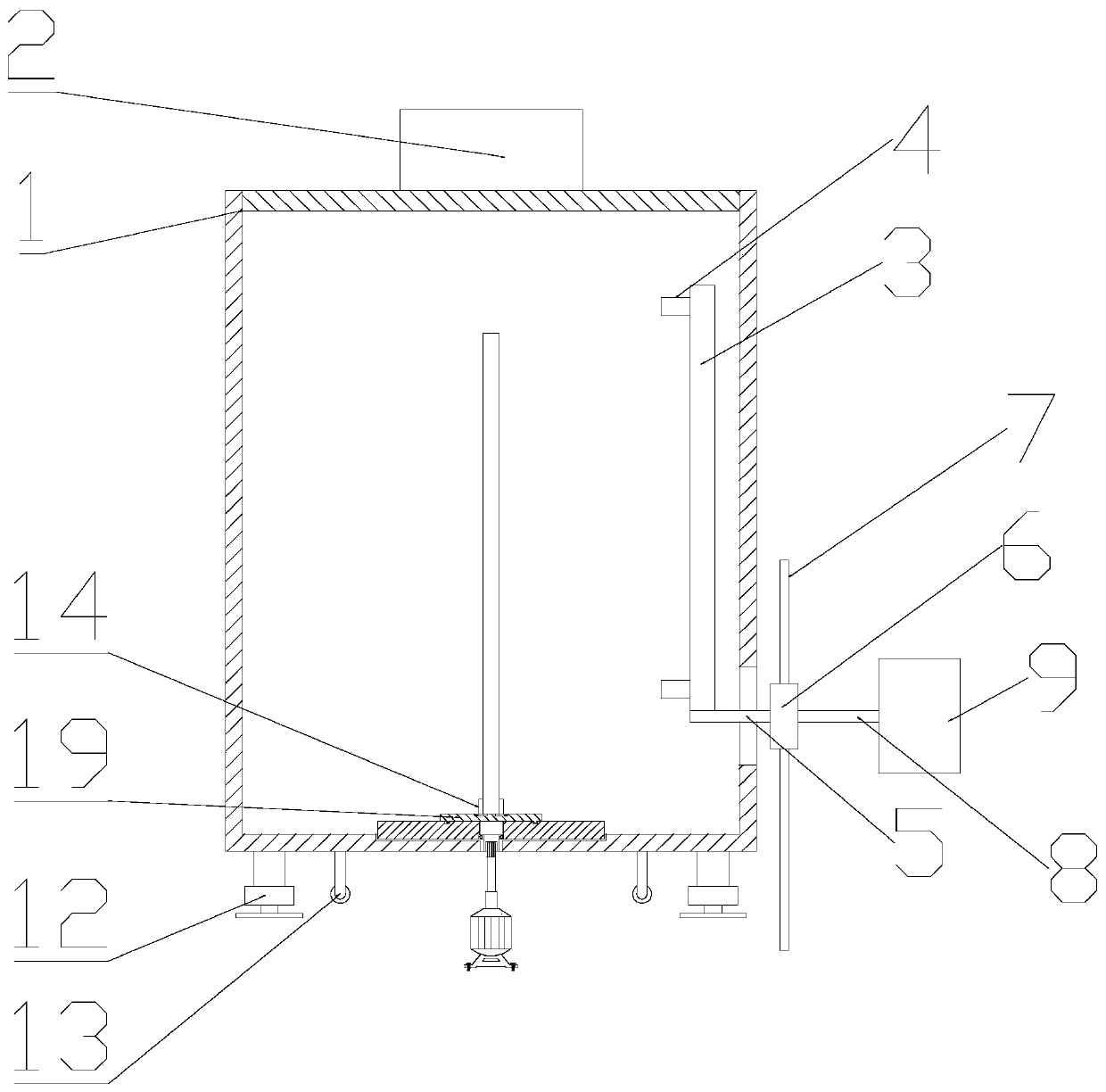
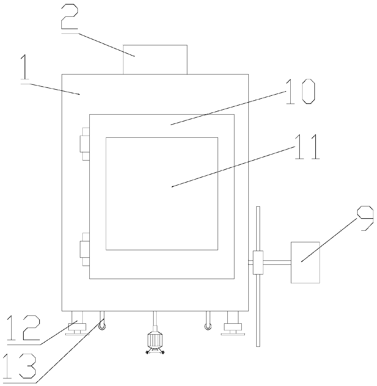
[0018] see figure 1 and figure 2 , a kind of plate paint spraying device for building, comprises paint spraying box 1, ventilating device 2, spray head installation frame 3, spray head 4 and spray head elevating bar 5, described spray paint box 1 is a cavity structure, and described paint spray box 1 upper end surface is provided with The ventilation device 2, the ventilation device 2 communicates with the paint spray box 1, the spray head mounting frame 3 is arranged on the right side of the inner cavity of the paint spray box 1, and the spray head mounting frame 3 is installed on the left end surface. The spray head 4, the bottom bolt of the spray head mounting frame 3 is fixed on the spray head lifting rod 5; the spray head lifting rod 5 extends out of the paint spray box 1 to the right and is welded and fixed with the lifting block 6, and the lifting block 6 is up and down Slidingly installed on the guide rail 7, the right end surface of the lifting block 6 is welded and...

Embodiment 2

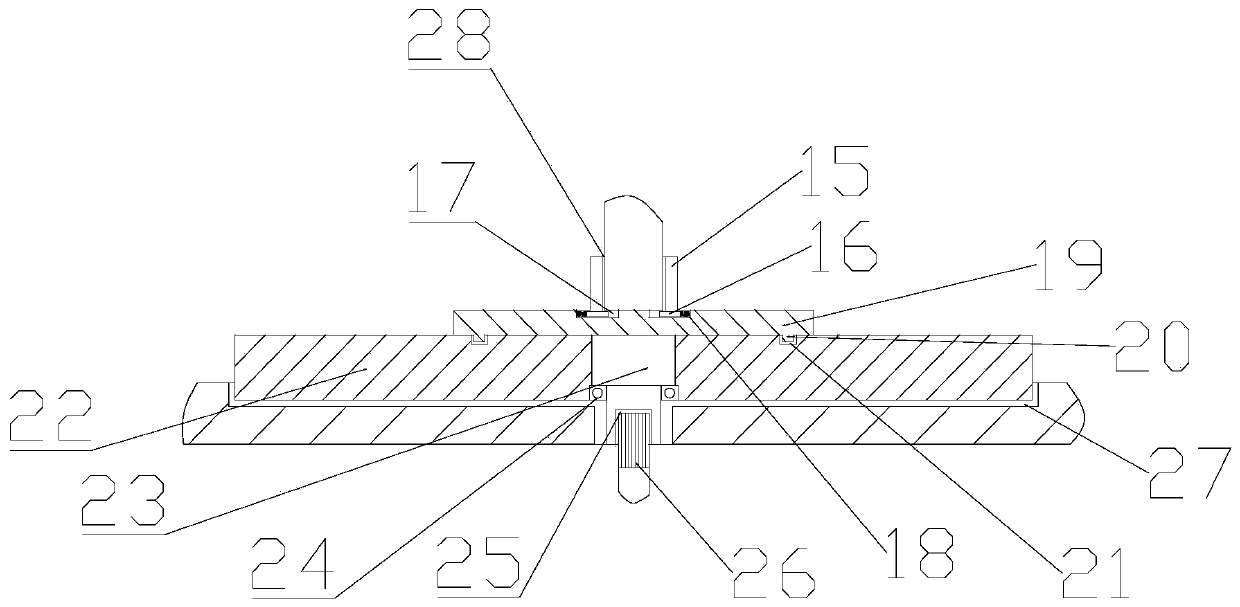
[0020] see image 3 , the fixing mechanism 14 includes a fixing plate 15, a slider 16, a chute 17 and a spring 18, the bottom of the fixing plate 15 is welded and fixed on the upper end surface of the slider 16, and the lower end surface of the slider 16 is slidably installed on the In the chute 17, the chute 17 is opened on the mounting seat 19, the spring 18 is also placed in the chute 17, when installing the plate, only need to insert the plate into the left and right fixed plates 15 It is convenient and fast, and can be adapted to fix plates of different thicknesses; the fixing plate 15 is bonded with a backing plate 28 near the side of the plate, which plays a buffering and protective effect, and prevents the fixing plate 15 from directly pressing the plate to cause the plate Surface wear; the bottom of the mounting seat 19 is processed with an annular slider 20, the annular sliding block 20 is slidably installed in the annular chute 21, and the annular chute 21 is opened...


PUM


Abstract

The invention relates to the technical field of building equipment, in particular to a building plate painting device. The building plate painting device comprises a paint spraying box, a ventilatingdevice, a spray head mounting device, a spray head and a spray head lifting rod. The spray head lifting rod extends out of the paint spraying box rightwards, and is welded and fixed to a lifting block, the lifting block is mounted on a guide rail in a vertical sliding manner, and the right end face of the lifting block is welded and fixed to the left end of a connecting rod. The right end of the connecting rod is mounted on a lifting motor. A fixing mechanism is arranged at the bottom of a cavity in the paint spraying box, and mounted on a mounting base. A door is mounted on the front end faceof the paint spraying box through a hinge, and an observation opening is formed in the door. A hydraulic supporting seat and universal wheels are fixed to the lower end face of the paint spraying boxthrough bolts. The building plate painting device is simple in structure, existing equipment can be transformed conveniently, paint spraying operation on the two faces of a plate can be completed conveniently and fast at a time, and the plate painting efficiency is greatly improved; and high practicality is achieved, and the application range is wide.

Description

technical field [0001] The invention relates to the technical field of building equipment, in particular to a painting device for building boards. Background technique [0002] Paint is a chemical mixture coating that can firmly cover the surface of objects for protection, decoration, marking and other special purposes. It is widely used in modern technology and industrial fields, especially in the construction industry. In order to make building materials better and more excellent Performance, building materials, especially boards, usually need to be painted. [0003] Chinese patent (notification number: CN207667907U, announcement date: 2018.07.31) discloses a panel paint spraying device for construction and decoration, including a paint spray box, a water curtain panel, a spray cup reciprocating machine and an electrostatic spray head. A spray cup reciprocating machine is installed on the side, and an electrostatic spray head is installed on the spray cup reciprocating ma...

Claims


Application Information

Patent Timeline
Patent Type & Authority Applications(China)
IPC IPC(8): B05B13/02B05B16/40B05B13/04
Inventor 陶军军
Owner 陶军军
Learn More