Mold

A mold and mold core technology, applied in the field of injection molds and molds, can solve problems such as trapped air and affect the quality of product injection molding, and achieve the effect of improving the quality of injection molding and eliminating the phenomenon of trapped air

Inactive Publication Date: 2019-05-21
AAC PRECISE MFG TECH CHANGZHOU
View PDF4 Cites 1 Cited by
  • Summary
  • Abstract
  • Description
  • Claims
  • Application Information

AI Technical Summary

Problems solved by technology

[0002] Existing industrial products usually adopt the injection molding process, and the most important thing in the injection molding process is the structure of the mold. In the production process of industrial products, when the mold is closed and injected with hot-melt plastic, air is often brought in, and the hot-melt When the shaped plastic flows in the cavity of the mold, it will squeeze the air. If the air cannot be effectively discharged, it will cause trapped air, which will affect the injection molding quality of the product.

Method used


Image

  • Mold
  • Mold
  • Mold

Examples


Embodiment

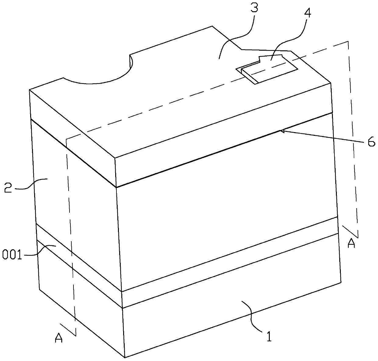
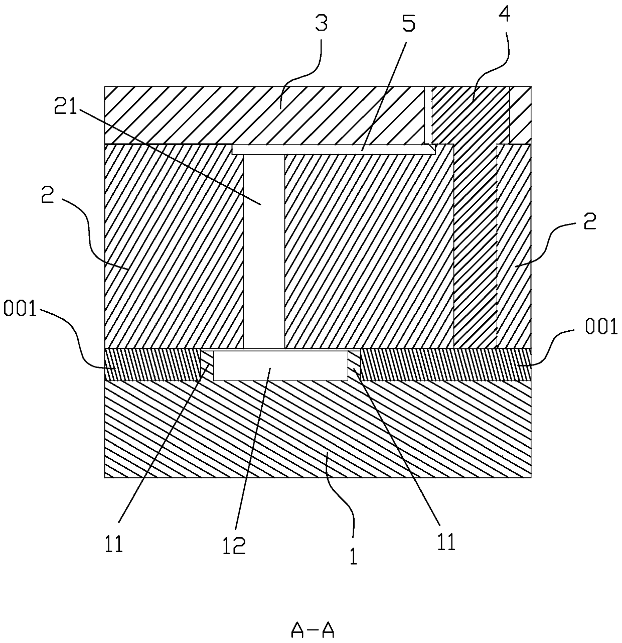
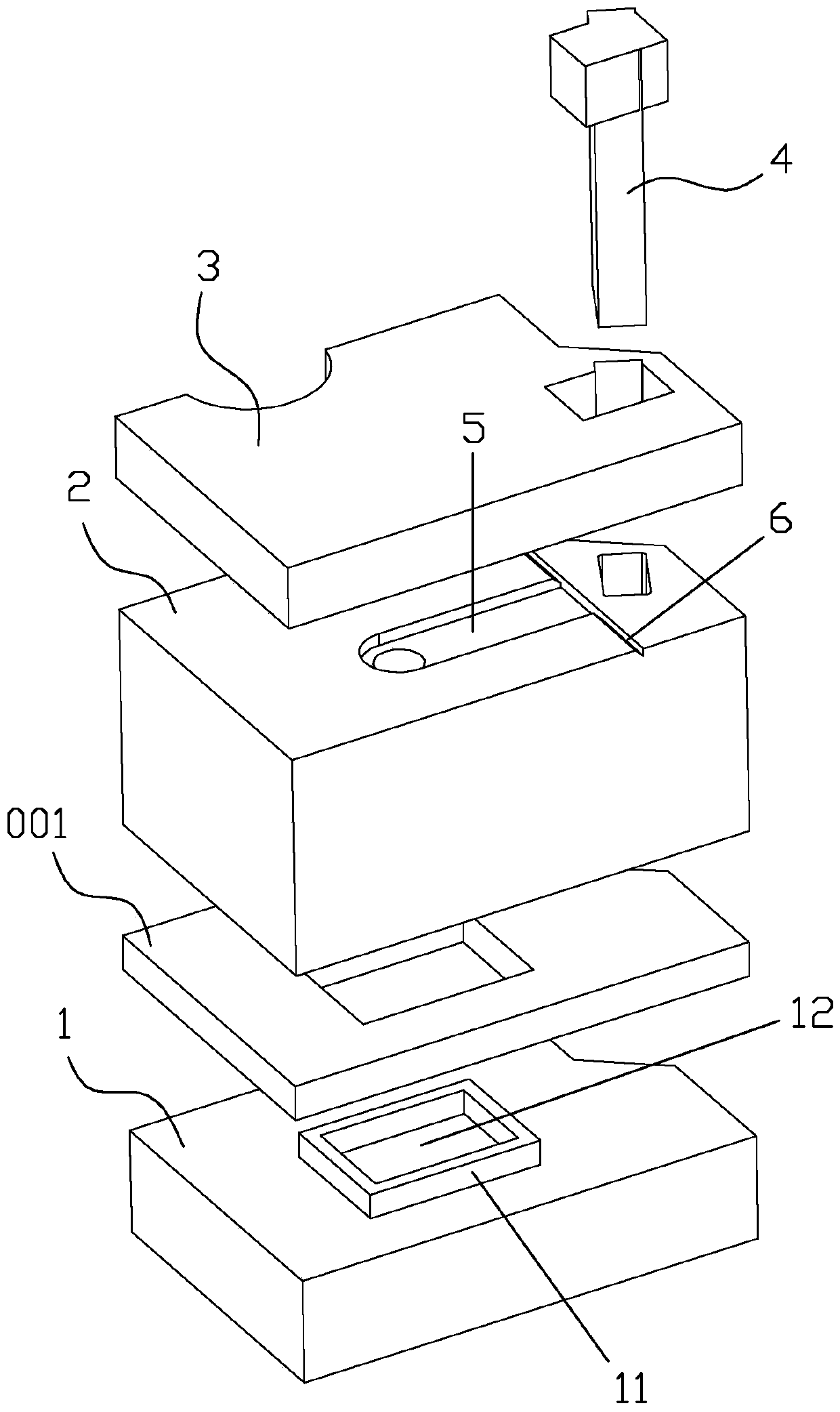
[0016] In this example, if Figure 1-3 As shown, the mold includes: a first mold core 1 and a second mold core 2, the first mold core 1 is provided with a sealant enclosing wall 11 on the joint surface, and the second mold core 2 is provided with a row that communicates with the outside world. The air channel 21, the exhaust channel 21 and the sealant enclosing wall 11 are arranged correspondingly. During injection molding, a mold cavity is formed between the first mold core 1 and the second mold core 2, and the sealant enclose wall 11 and the second mold core An exhaust cavity 12 is formed between the mold cores 2, and the sealing wall 11 isolates the molten plastic in the cavity from the exhaust cavity 12, and the end surface of the sealing wall 11 and the second mold core 2 There is a gap for the air in the mold cavity to pass into the exhaust cavity 12, and the exhaust channel 21 communicates with the exhaust cavity 12 through the gap, and the exhaust channel 21 allows the...


PUM


Abstract

The invention provides a mold comprising a first mold core and a second mold core. A glue sealing surrounding wall is arranged on one side of a mold closing surface of the first mold core, an exhaustpassage is arranged on the second mold core, and the exhaust passage and the glue sealing surrounding wall are correspondingly arranged. When injection mold closing is performed, a cavity is formed between the first mold core and the second mold core, an exhaust cavity is formed between the glue sealing surrounding wall and the second mold core, the glue sealing surrounding wall isolates molten plastic in the cavity outside the exhaust cavity, a gap for leading air in the cavity into the exhaust cavity is arranged between the end face of the glue sealing surrounding wall and the second mold core, and the exhaust passage allows air in the exhaust cavity to flow outside the second mold core. The glue sealing surrounding wall can prevent the molten plastic from entering the exhaust cavity, the air in the cavity enters the exhaust cavity from the gap between the glue sealing surrounding wall and the second mold core, then the air is discharged outside the second mold core from the exhaustcavity through the exhaust passage, the air trapping phenomenon in the injection mold is prevented, and the injection molding quality of the product is improved.

Description

technical field [0001] The invention belongs to the technical field of injection molds, in particular to a mold. Background technique [0002] Existing industrial products usually adopt the injection molding process, and the most important thing in the injection molding process is the structure of the mold. In the production process of industrial products, when the mold is closed and injected with hot-melt plastic, air is often brought in, and the hot-melt When the shaped plastic flows in the cavity of the mold, it will squeeze the air. If the air cannot be effectively discharged, it will cause air trapping, which will affect the injection molding quality of the product. Contents of the invention [0003] The technical problem to be solved by the present invention is to provide a mold, which aims to prevent air trapping during injection molding, so as to improve the quality of injection molding products. [0004] In order to solve the above-mentioned technical problems, t...

Claims


Application Information

Patent Timeline
IPC IPC(8): B29C45/34
Inventor 冯炉邵状
Owner AAC PRECISE MFG TECH CHANGZHOU
Why Eureka
Try Eureka