A combined flame stabilizer with adjustable concave cavity vortex structure and its working method

A flame stabilizer, adjustable technology, applied in the direction of combustion method, lighting and heating equipment, continuous combustion chamber, etc., can solve the problems of insufficient flameout performance at lean point, high ignition and flame stability performance, etc., to ensure flame stability performance , widen the limit of flameout, and accelerate the effect of spreading

Active Publication Date: 2020-01-10
NANJING UNIV OF AERONAUTICS & ASTRONAUTICS +1
View PDF6 Cites 0 Cited by
  • Summary
  • Abstract
  • Description
  • Claims
  • Application Information

AI Technical Summary

Problems solved by technology

[0005] Purpose of the invention: the present invention provides a combined flame stabilizer with an adjustable concave cavity vortex structure, and the concave cavity vortex structure can be adjusted by changing the relative position between the radial flame stabilizer and the concave cavity of the outer concave cavity flame stabilizer , obtain higher combustion chamber ignition and flame stability performance, and solve the problem of insufficient flameout performance at the lean point of the existing conventional concave cavity / support plate stabilizer at relatively low temperature and high-speed airflow

Method used


Image

  • A combined flame stabilizer with adjustable concave cavity vortex structure and its working method
  • A combined flame stabilizer with adjustable concave cavity vortex structure and its working method
  • A combined flame stabilizer with adjustable concave cavity vortex structure and its working method

Examples


Embodiment 1

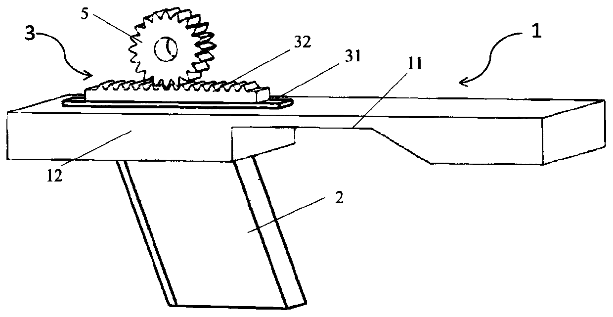
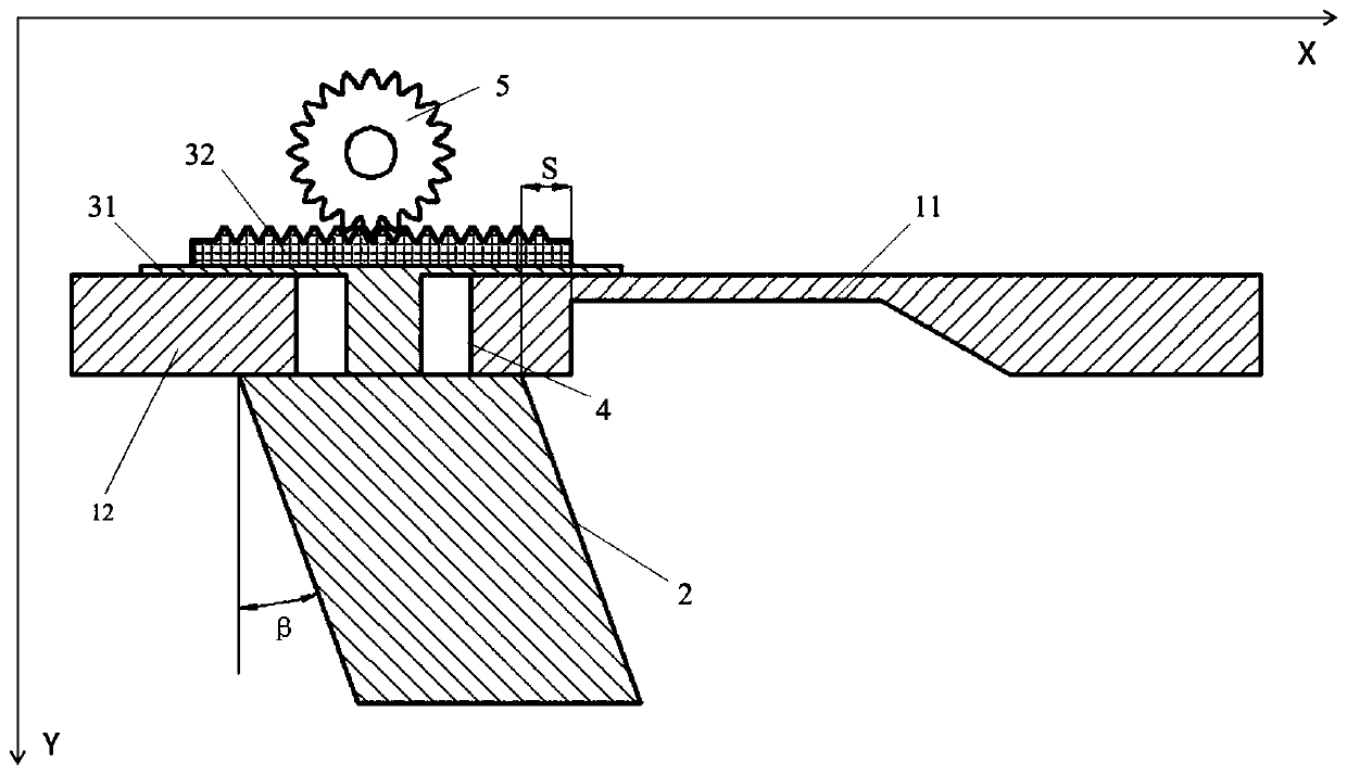
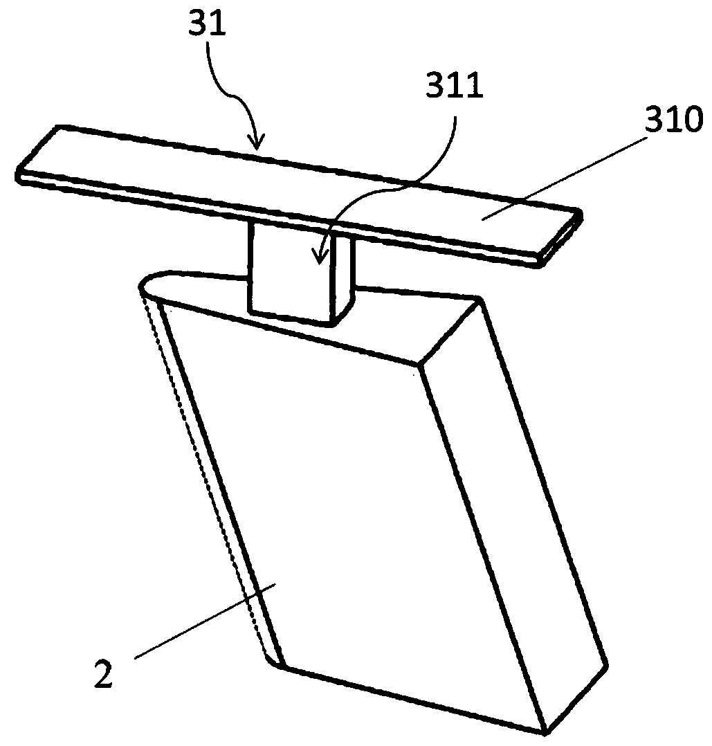
[0023] Embodiment 1: as figure 1 As shown, the combined flame stabilizer of the adjustable cavity vortex structure of the present invention, the combined flame stabilizer is composed of an outer concave cavity flame stabilizer 1, a radial flame stabilizer 2, and is used to adjust the radial flame stabilizer 2 is composed of an adjustment mechanism 3 relative to the axial relative position of the outer cavity flame stabilizer 1 and a guide groove 4 for limiting the axial maximum travel of the adjustment mechanism 3 .

[0024] The outer cavity flame stabilizer 1 is composed of a horizontal section 12 extending horizontally at the front end and a cavity section 11 at the rear end of the horizontal section 12. A guide groove 4 is opened on the horizontal section, and the guide groove 4 runs through the thickness direction of the horizontal section 12. One end of the adjustment mechanism 3 is located on the outer wall of the horizontal section, and the other end passes through the ...


PUM


Abstract

The invention discloses a combined flame stabilizer capable of adjusting a cavity vortex area structure. The combined flame stabilizer comprises an outer cavity flame stabilizer, a radial flame stabilizer, an adjusting mechanism used for adjusting the axial relative position of the radial flame stabilizer to the outer cavity flame stabilizer, and a guiding groove used for limiting the axial maximum stroke of the adjusting mechanism; the outer cavity flame stabilizer comprises a cavity section and a horizontal section horizontally and axially extending out towards the front end along the cavitysection; and the radial flame stabilizer is located on the inner wall face of the horizontal section. The cavity vortex area structure is adjusted by changing the relative position between the radialflame stabilizer and a cavity, high combustion chamber ignition and flame stability performance is achieved, and the problem that lean oil ignition and flameout performance of an existing conventional cavity / supporting plate stabilizer is insufficient under the relative low temperature and high-speed airflow is solved.

Description

technical field [0001] The invention relates to an afterburner combustion chamber of a turbofan engine, a combustion chamber of a sub-combustion ramjet engine and a multi-mode combustion chamber of a turbofan / ramjet combined cycle engine, in particular to a combined flame stabilizer with an adjustable concave cavity swirl structure and its operation method. Background technique [0002] Turbine-based combined cycle (TBCC) as an air-breathing engine has the advantages of wide flight range, conventional takeoff and landing, and reusability, and is considered to be the most promising hypersonic vehicle at this stage. powerplant. Due to the large variation of the bypass ratio in the entire working range, the flow conditions of low flow temperature and excessive local flow velocity in the multi-mode combustion chamber of the TBCC engine bring difficulties to the ignition and flame stability inside the multi-mode combustion chamber. . [0003] With the increase of the airflow v...

Claims


Application Information

Patent Timeline
Patent Type & Authority Patents(China)
IPC IPC(8): F23R3/22
Inventor 范育新缪俊杰陶华刘天池陈忠良
Owner NANJING UNIV OF AERONAUTICS & ASTRONAUTICS
Why Eureka
Try Eureka