
Electronically controllable pneumatic brake system in a utility vehicle and method for electronically controlling a pneumatic brake system in a utility vehicle

A technology of pneumatic braking and mode control, which is applied in the direction of braking control system, ABS control system, braking transmission device, etc., and can solve the problems of increasing the cost of installation

Active Publication Date: 2019-05-21
WABCO EURO BVBA SPRL
View PDF10 Cites 0 Cited by
  • Summary
  • Abstract
  • Description
  • Claims
  • Application Information

AI Technical Summary

Problems solved by technology

The disadvantage of this solution is that a very large number of additional components are required in order to retrofit an existing pneumatic parking brake, for example the pneumatic implementation of the actuation of the 3 / 2-way valve, which additionally increases the retrofitting costs

Method used


Image

  • Electronically controllable pneumatic brake system in a utility vehicle and method for electronically controlling a pneumatic brake system in a utility vehicle
  • Electronically controllable pneumatic brake system in a utility vehicle and method for electronically controlling a pneumatic brake system in a utility vehicle
  • Electronically controllable pneumatic brake system in a utility vehicle and method for electronically controlling a pneumatic brake system in a utility vehicle

Examples


Embodiment Construction

[0043] specific implementation plan

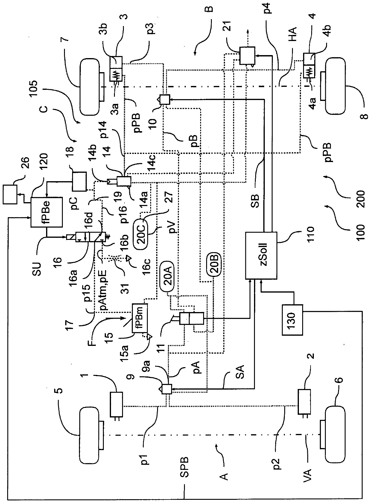
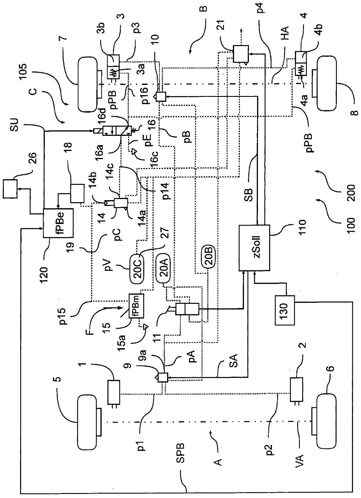
[0044] in accordance with Figure 1a and Figure 1b In the embodiment of the present invention, a cross-sectional view of an electro-pneumatic braking system 100 of a vehicle 200 is shown in block diagram form, wherein the electro-pneumatic braking system is designed as an EBS braking system 100, that is, in standard operation Ways to implement braking regulations. For this purpose, EBS braking system 100 has four wheel brakes 1 , 2 , 3 , 4 which serve to brake wheels 5 , 6 , 7 , 8 of vehicle 200 . Three brake circuits A, B, C are provided for braking, to which pressure medium reservoirs 20A, 20B, 20C are assigned correspondingly, in order to supply the respective brake circuits A, B, C with a reserve pressure medium 27 and thus realize the respective Wheel brakes 1, 2, 3, 4 build up brake pressures p1, p2, p3, p4, pPB.

[0045] In a first service brake circuit A, wheel brakes 1 , 2 are mounted on wheels 5 , 6 of front axle VA, wherein ...


PUM


Abstract

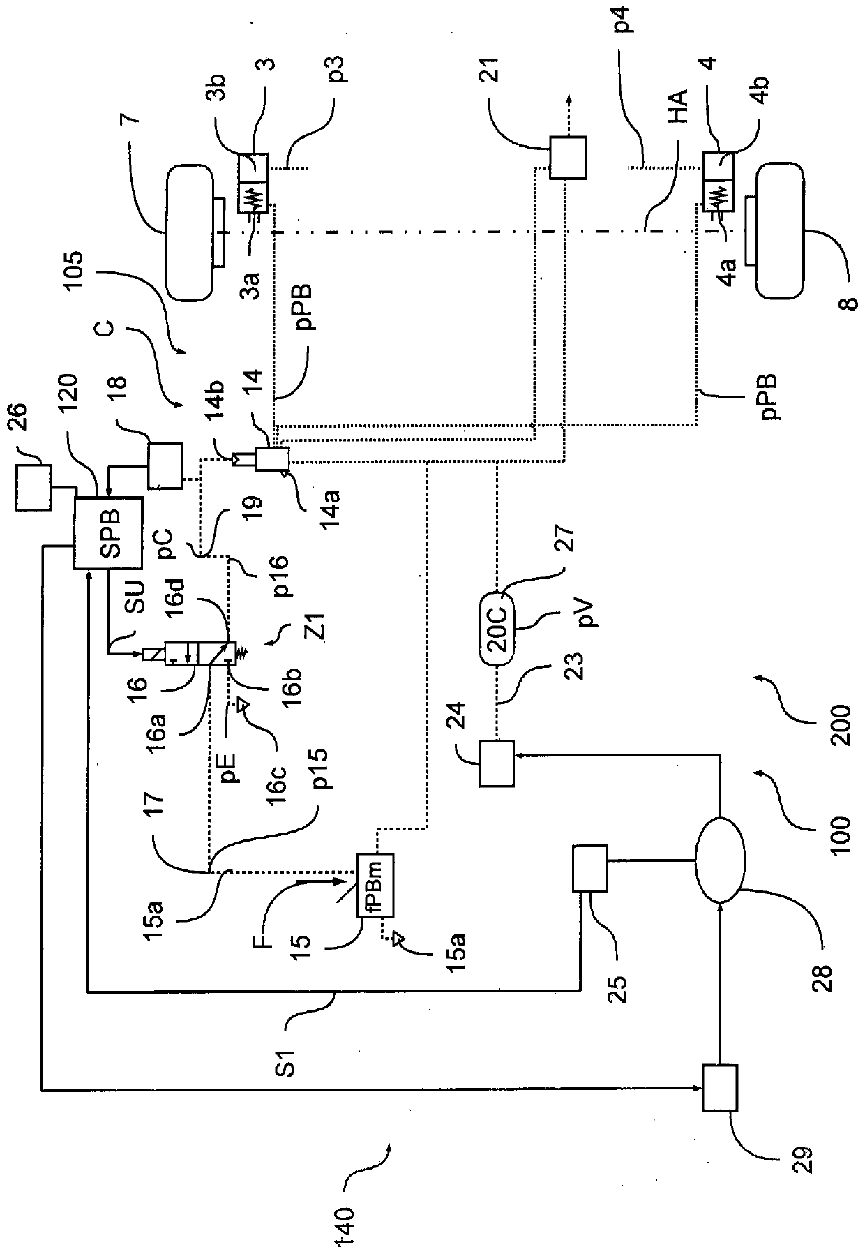
The invention relates to an electronically controllable pneumatic brake system (100) in a vehicle (200), at least comprising: wheel brakes (1, 2, 3, 4), where wheel brakes (3, 4) of at least one vehicle axle (HA, VA) comprise spring-type brake cylinders (3a, 4a), an electronically controllable monostable bypass valve (16), where the monostable bypass valve (16) is arranged between a manually actuatable parking brake valve (15) and the spring-type brake cylinders (3a, 4a) in such a way that, in a first switching position (Z1), the monostable bypass valve (16) controls a bypass control pressure(p16) according to an actuation pressure (p15) produced by the parking brake valve (15), in order to implement a manually pre-defined parking brake force (fPBm), and, in a second switching position, it controls a bypass control pressure (p16) according to a prevailing bleed pressure (pE) in a bypass bleed connection (16c), in order to implement an electrically pre-defined parking brake force (fPBe), where a parking brake brake pressure (pPB) controlled on the spring-type brake cylinder (3a, 4a) can be adjusted according to the bypass control pressure (p16), and where the monostable bypass valve (16) automatically shifts into the first switching position (Z1) without electrical control.

Description

technical field [0001] The invention relates to an electronically controllable pneumatic braking system in a commercial vehicle and to a method for electronically controlling a pneumatic braking system. Background technique [0002] In vehicles with a pneumatic brake system, in particular commercial vehicles, the electronic axle modulator can be actuated by the control unit (ECU) in order to provide the brake pressure. In this case, electronic actuation takes place either as a function of the driver's desire predetermined by the foot brake valve or as a function of an automatically predetermined vehicle target delay. The corresponding brake pressure is generated pneumatically by the axle modulator, which is assigned to the brake cylinders of the working brakes of the brake system. [0003] Alternatively, the axle modulators can also be actuated pneumatically, in particular, the foot brake valves prescribe to the axle modulators a control pressure corresponding to the driver...

Claims


Application Information

Patent Timeline
IPC IPC(8): B60T13/68B60T13/66
CPCB60T13/662B60T13/683B60T7/12B60T8/17B60T8/94B60T13/268B60T13/385B60T2270/10B60T2270/402B60T2270/403B60W10/184B60W10/188
Inventor 奥利弗·伍尔夫
Owner WABCO EURO BVBA SPRL
Learn More