Installation device for mounting in ceiling

A ceiling and installer technology, applied in the parts of lighting devices, lighting devices, supporting machines, etc.

Active Publication Date: 2019-05-21
ABB (SCHWEIZ) AG
View PDF7 Cites 0 Cited by
  • Summary
  • Abstract
  • Description
  • Claims
  • Application Information

AI Technical Summary

Problems solved by technology

As a result, there is a danger that the mounting device is pushed out of the opening in the ceiling due to the action of force generated by the lines and that the flange-like housing section of the mounting device no longer rests flush against the ceiling or material. bottom of the board

Method used


Image

  • Installation device for mounting in ceiling
  • Installation device for mounting in ceiling
  • Installation device for mounting in ceiling

Examples


Embodiment Construction

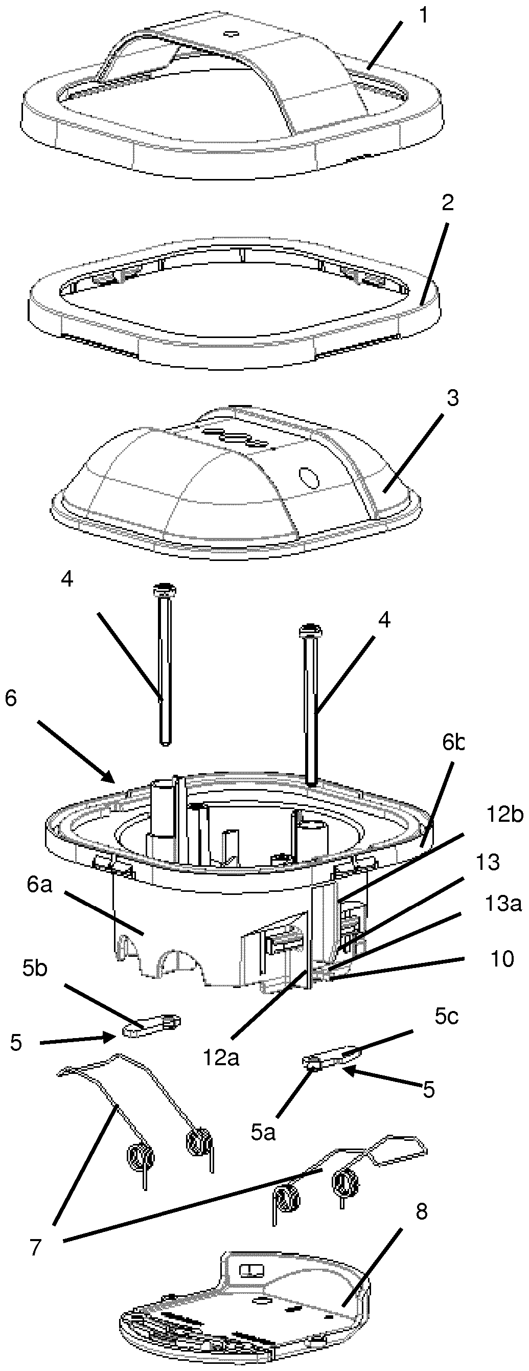
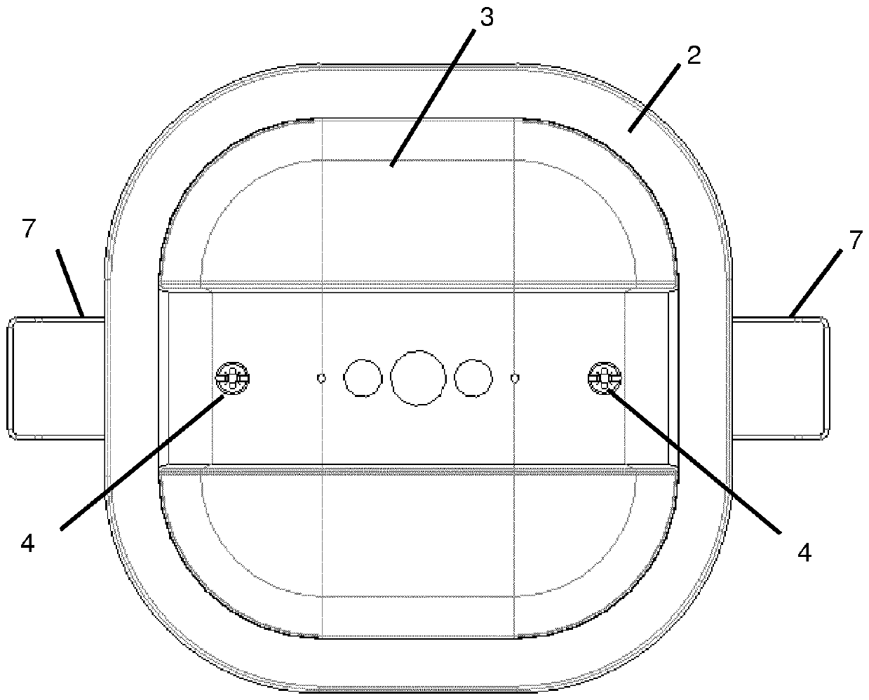
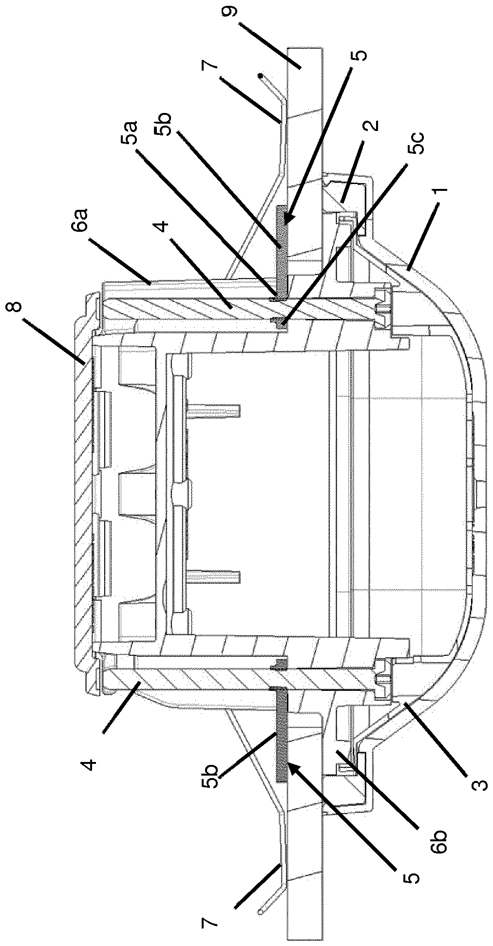
[0026] as in Figures 1 to 6As shown in , the mounter for fitting in the only partly shown opening 16 of a ceiling 9 formed of a plate-like material such as, for example, wood or plasterboard and having an inner space 17 and an outer space 18 comprises a housing Body 6, which has a first housing section 6a. The first housing section 6 a has a smaller diameter than the opening 16 . Furthermore, a flange-like second housing section 6 b is formed on the housing 6 , which has an enlarged diameter relative to the opening 16 and which rests flush against the first housing section 6 a after being pushed in. At the bottom surface of the ceiling 9, when the first housing section 6a is as in figure 2 when fully pushed into the opening as shown in . In the region of the first housing section 6a, two diametrically opposite opening arms 7 are pivotably fixed, which are radially extended by means of spring elastic means in the form of coil springs which are not shown in more detail. lo...


PUM


Abstract

An installation device for mounting in an opening (16) of a building ceiling (9) formed from panel-shaped material, with a housing (6) which has a housing portion (6a) which can be pushed into the opening (16), and a second, flange-like housing portion (6b) which is arranged outside the opening (16) and has a larger diameter than the opening (16) and which, after being pushed in, can be brought into contact flush with the lower side of the ceiling (6), and with spring-loaded expansion arms (7) which are arranged in the region of the first housing portion (6a) and are forced by spring-elastic means from a radially inner insertion position into a radially extended expansion position, is characterized in that a claw element (5) having an eccentric threaded bore (5a) formed in the latter is arranged on the first housing portion (6a) and, by rotation of a screw (4) engaging in the threaded bore (5a) in a first direction of rotation, is movable in the axial direction towards the flange-likehousing portion (6b) from an insertion position into a clamping position.

Description

technical field [0001] The invention relates to an installation device for ceiling mounting according to the preamble of claim 1 . Background technique [0002] In building installation technology there are various mounts, such as, for example, motion detectors, smoke detectors, light sources, etc., which are mounted on the ceiling of a room. In the case of room ceilings, which are usually produced by fitting material panels such as for example plasterboard beneath a load-bearing building roof (Gebäudedecke) formed, for example, of concrete, another There is a hollow interior space or gap on the side. For assembly, such a mount is pushed with its one end through an opening in the material sheet into the gap until the flange-like housing section formed on the mount rests flush against the underside of the ceiling and the externally visible part of the mount is in the external space of the ceiling. [0003] It is known from the prior art that the mount is held autonomously ...

Claims


Application Information

Patent Timeline
Patent Type & Authority Applications(China)
IPC IPC(8): F16M13/02F21V21/04
CPCF16M13/027F21V21/043
Inventor F.魏贝尔M.维泽W.利森M.埃维尔斯
Owner ABB (SCHWEIZ) AG
Why Eureka
Try Eureka