Detection and validation of objects from sequential images from camera by means of homographs

A homography matrix and camera technology, applied in the field of driver assistance systems, can solve problems such as system performance degradation

Pending Publication Date: 2019-05-21
CONTI TEMIC MICROELECTRONIC GMBH
View PDF5 Cites 2 Cited by
  • Summary
  • Abstract
  • Description
  • Claims
  • Application Information

AI Technical Summary

Problems solved by technology

However, new vehicle designs and altered structural forms may lead to severe degradation of system performance and require general object recognition methods

Method used


Image

  • Detection and validation of objects from sequential images from camera by means of homographs
  • Detection and validation of objects from sequential images from camera by means of homographs
  • Detection and validation of objects from sequential images from camera by means of homographs

Examples


Embodiment Construction

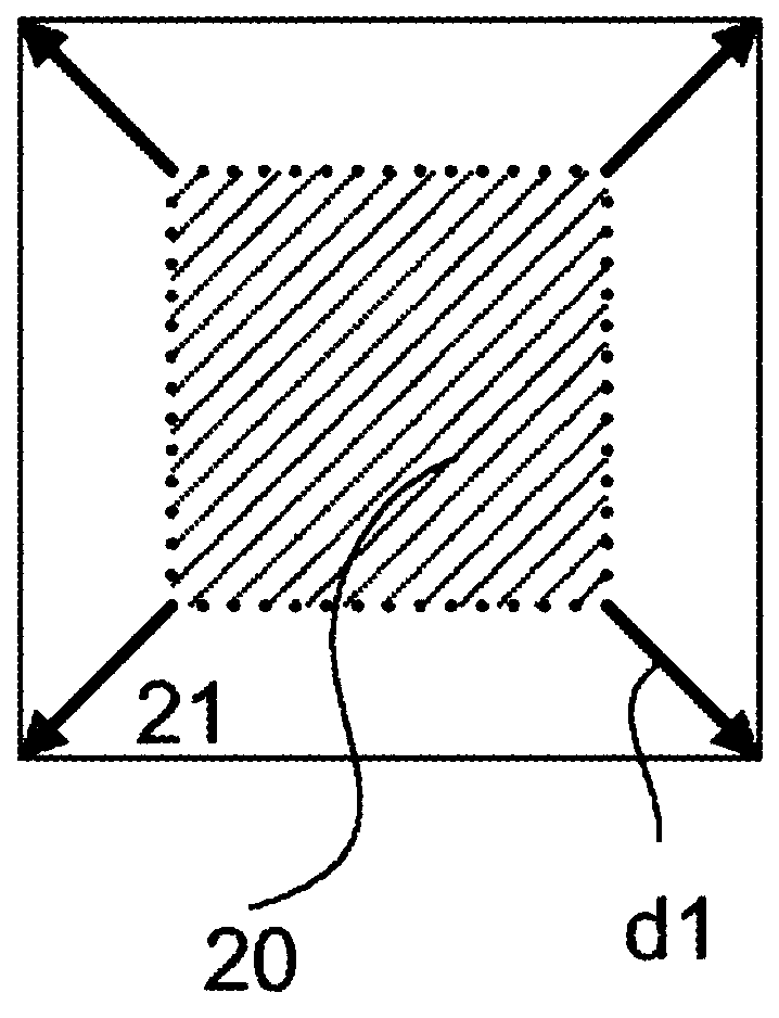
[0055] figure 1 A back plane (English: back plane) is schematically depicted in , which occupies the hatched area ( 20 , shown by dashed line) at a first time point t−1 . At a subsequent point in time t, the distance between the on-board camera and the rear plane decreases, which results in a deformation of the region of the rear plane in the image ( 21 , indicated by a solid line), indicated by the arrow ( d1 ). The scaling or magnification of the area (20; 21) is the result of the relative movement of the on-board camera with respect to the back plane.

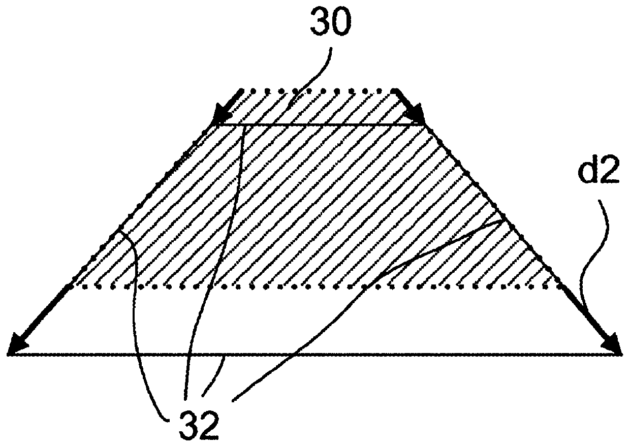
[0056] figure 2 A ground plane (English: ground plane) is schematically depicted, which occupies the hatched area (30, shown by dashed lines) at a first time point t−1. This may be a portion of the roadway surface on which the vehicle travels. Due to the self-motion of the on-board camera, the area (in the image) changes at a subsequent point in time t, resulting in a deformation of the area ( 32 ) of the base plane outl...


PUM


Abstract

The invention relates to a method and to a device for identifying objects from images from a camera and can be used in particular in camera-based driver assistance systems. The method for detecting objects from a series of images from a vehicle camera comprises the following steps: a) capturing a series of images by means of the vehicle camera, b) determining corresponding features in two consecutive images, d) determining a plurality of planes in space by associating adjacent corresponding features with a plane in space, f) detecting objects while taking into account the planes determined instep d). According to a preferred embodiment, the method comprises the following step: c) computing homographs for adjacent corresponding features for determining the plurality of planes; and / or d2) associating adjacent corresponding features with a bottom plane, a back wall plane, or a side wall plane. Because the method according to the invention can be designed to be very fast, generic object detection or scene interpretation is possible for nearly the whole image in real time.

Description

technical field [0001] The invention relates to a method for recognizing objects from camera images and can be used in particular in camera-based driver assistance systems. Background technique [0002] Most vehicle identification systems according to the current state of the art are based on classification. A classification-based system re-identifies vehicles or vehicle parts it has seen in training data. However, new vehicle designs and changed structural forms may lead to severe degradation of system performance and require general object recognition methods. [0003] US 2014 / 0161323 A1 describes a method for generating dense three-dimensional structures in the road surroundings from images captured with a monocular camera. [0004] EP 2 993 654 A1 describes a method for giving a forward collision warning (FCW) from a camera image. In this case, an image portion is analyzed, to which the own vehicle will arrive within a predetermined time interval. If an object is det...

Claims


Application Information

Patent Timeline
Patent Type & Authority Applications(China)
IPC IPC(8): G06K9/00
CPCG06V20/58G06V10/40B60W50/14B60W2420/42G06T2207/30261
Inventor M·沃尔特
Owner CONTI TEMIC MICROELECTRONIC GMBH
Why Eureka
Try Eureka