How to make iron chips
A manufacturing method and technology of iron chips, applied in the direction of manufacturing stator/rotor body, magnetic circuit shape/style/structure, magnetic circuit static parts, etc. gender issues
- Summary
- Abstract
- Description
- Claims
- Application Information
AI Technical Summary
Problems solved by technology
Method used
Image

Examples
no. 1 Embodiment approach
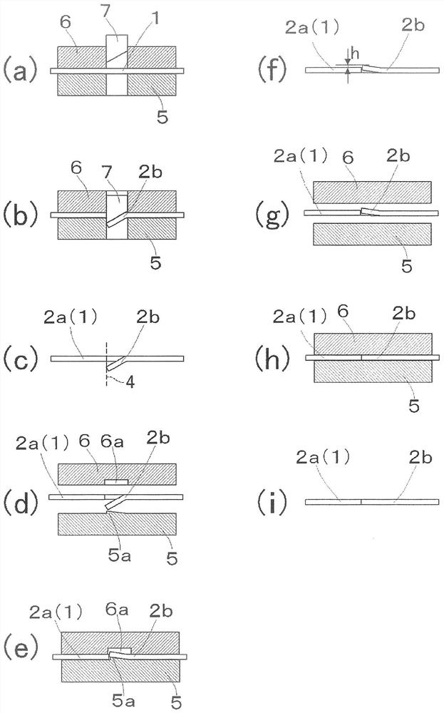
[0066] The stator core sheet 2b passes through such as figure 2 Manufactured according to the process shown. First, if figure 2 As shown in (a), the raw material 1 is clamped between the die 5 and the stripping plate 6 installed in the press apparatus which is not shown in figure. The stamping device comprises a punch 7 that is telescopic relative to the raw material 1 . When the raw material 1 is clamped between the die 5 and the release plate 6, as figure 2 As shown in (b), the punch 7 is pressed down (advances to the raw material 1), and it abuts on the stator core piece 2b. As a result, the stator lamination 2b is cut and bent, as figure 2 As shown in (c), the boundary line 4 between the stator core sheet 2a (raw material 1) and the stator core sheet 2b is cut out.
[0067] As above, the notch bending process is completed. In addition, at this time, the stator core sheet 2b bends downward in the vicinity of the boundary line 4, and a step difference occurs betwee...
no. 2 Embodiment approach
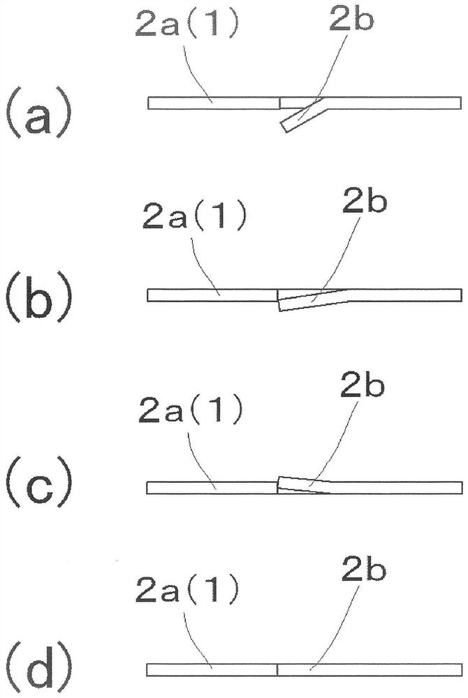
[0073] In the first embodiment, an example was shown in which the reverse bending step was performed without going through other steps after the notch bending step, and the bending recovery step was finally performed, but the present invention is not limited thereto. For example, if image 3 As shown, the bending recovery process may be performed after the notch bending process, followed by the reverse bending process, and finally the bending recovery process may be performed again.
[0074] image 3 (a) is a figure which shows the state of the raw material 1 after completion|finish of a notch bending process, and is the same as that of the said 1st Embodiment. figure 2 (c) Corresponding figure. In the method of manufacturing the core sheet according to the second embodiment, in image 3 The raw material 1 shown in (a) is subjected to initial bending recovery processing. If the bending recovery processing is carried out, as image 3 As shown in (b), the downward bending ...
no. 3 Embodiment approach
[0076] In the first embodiment, in the reverse bending process, an example was shown in which the upwardly bent portion of the stator core piece 2b was housed in the recess 6a using the stripper plate 6 provided with the recess 6a. However, the release plate 6 used in the reverse bending process is not limited to the structure provided with such a recess 6a. For example, it is also possible to Figure 4 As shown in (a), the through-hole 6b which penetrates the release plate 6 is included. The through-hole 6 b of the stripping plate 6 is provided at a position corresponding to the protrusion 5 a included in the die 5 . In this case, the portion of the stator core piece 2b bent upward by being pressed by the protrusion 5a of the die 5 is housed in the through hole 6b. Additionally, for example if Figure 4 As shown in (b), you may provide the slider 6c which can expand and contract with respect to the stripping plate 6, and may bridge the spring 6d between the stripping plate...
PUM
 Abstract
Description
Claims
Application Information
 - R&D Engineer
- R&D Manager
- IP Professional
- Industry Leading Data Capabilities
- Powerful AI technology
- Patent DNA Extraction
Browse by: Latest US Patents, China's latest patents, Technical Efficacy Thesaurus, Application Domain, Technology Topic.
© 2024 PatSnap. All rights reserved.Legal|Privacy policy|Modern Slavery Act Transparency Statement|Sitemap