
Exposure device and exposure method

A technology of exposure device and light source, which can be applied in the direction of photolithography exposure device, microlithography exposure equipment, photolithography mask, etc., can solve problems such as bending and exposure accuracy reduction

Active Publication Date: 2016-04-06
MURATA MFG CO LTD
View PDF6 Cites 0 Cited by
  • Summary
  • Abstract
  • Description
  • Claims
  • Application Information

AI Technical Summary

Problems solved by technology

When the size of the glass mask increases, since the mask holder supports the glass mask only from the edge, it is easy to bend the glass mask due to its own weight
In the case where the glass mask is warped, the exposure accuracy is greatly reduced

Method used


Image

  • Exposure device and exposure method
  • Exposure device and exposure method
  • Exposure device and exposure method

Examples


Embodiment approach 1

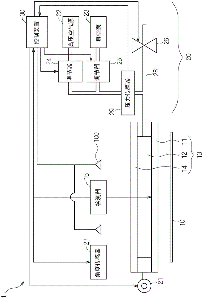
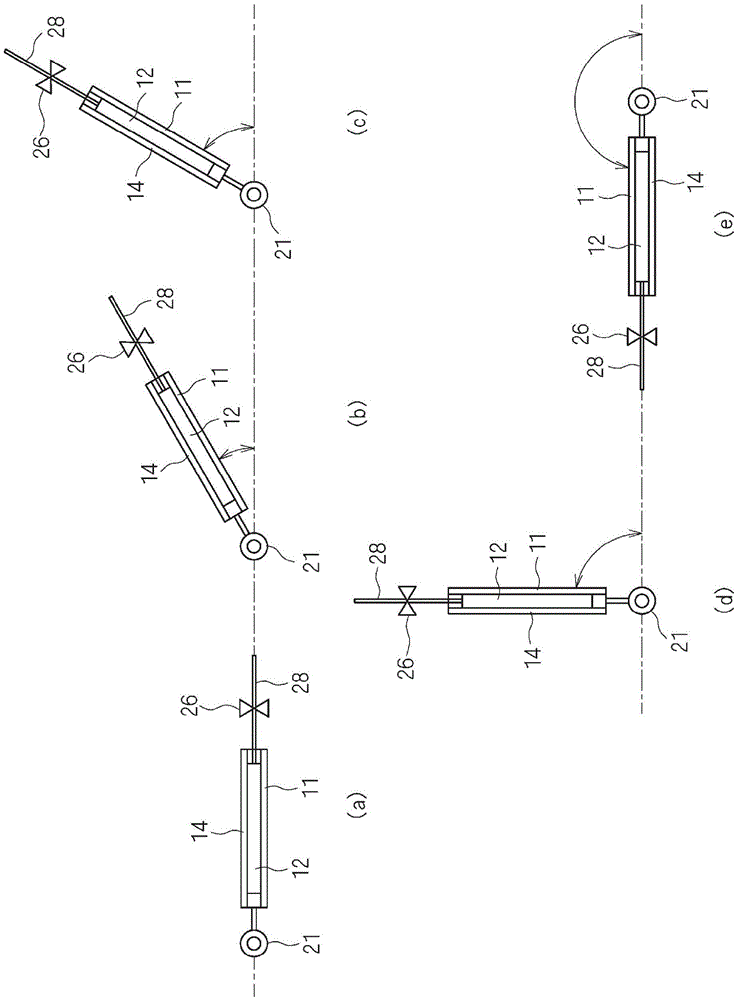
[0035] In the exposure apparatus according to Embodiment 1 of the present invention, in order to improve exposure accuracy, after adjusting the pressure (internal pressure) in the airtight space with the mask holder holding the optical plate tilted, the mask holder is restored to its original value. angle to expose the mask pattern on the workpiece 10 . Thus, the exposure apparatus according to Embodiment 1 includes a tilt mechanism at one end of the mask holder for tilting the mask holder holding the optical plate on which the mask pattern is provided. figure 1 It is a schematic diagram which shows the structure of the exposure apparatus concerning embodiment of this invention. in addition, figure 1 In , the imaging device and markers necessary for alignment with the workpiece are omitted, and only the structure necessary for adjusting the distance between the optical plate and the workpiece is described.

[0036] figure 1 Among them, the exposure apparatus 1 according to ...

Embodiment approach 2

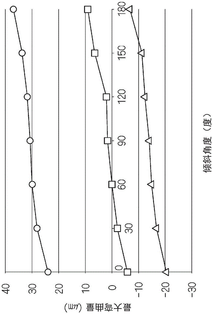
[0052] Since the configuration of the exposure apparatus according to Embodiment 2 of the present invention is the same as that of Embodiment 1, the same reference numerals are assigned and detailed description thereof will be omitted. Exposure apparatus 1 according to Embodiment 2 of the present invention differs from Embodiment 1 in that, according to image 3 In the shown relationship between the inclination angle of the mask holder 13 and the maximum amount of curvature of the optical plate 11 during exposure, for each inclination angle of the mask holder 13, the maximum amount of curvature of the optical plate 11 during exposure is determined to be zero. It is necessary to provide pressure into the airtight space 12 and store it.

[0053] That is, in the exposure apparatus 1 according to Embodiment 2 of the present invention, for each inclination angle of the mask holder 13 , the amount of deflection that needs to be supplied to the airtight space 12 in order to make the ...


PUM


Abstract

Provided are an exposure device and an exposure method such that it is possible to appropriately correct bending of a mask even when the mask size is large and perform exposure with high precision. An exposure device (1) according to the present invention comprises a light source (100), an optical plate (11) whereupon a mask pattern is disposed, and a mask holder (13) which holds the optical plate (11) and forms an airtight space on the side of the optical plate (11) toward the light source (100). Light from the light source (100) is projected upon the optical plate (11) so that the mask pattern is exposed onto a workpiece (10). The exposure device further comprises a pressure adjustment mechanism (20) which adjusts the pressure within the airtight space (12), and an incline mechanism (21) which inclines the mask holder (13) to a prescribed angle. With the mask holder (13) inclined at the prescribed angle by the incline mechanism (21), the pressure in the airtight space (12) is adjusted by the adjustment mechanism (20). Thereafter, the mask holder (13) is returned to the original angle and exposure is performed.

Description

technical field [0001] The present invention relates to an exposure device and an exposure method for manufacturing semiconductor devices, printed circuit boards, LCDs, and the like. In particular, it relates to an exposure apparatus and an exposure method capable of correcting a warp of a mask and improving finish quality even when the size of the mask is increased. Background technique [0002] When manufacturing semiconductor devices, printed circuit boards, LCDs, etc., a desired pattern is exposed to a workpiece through a glass mask having a predetermined pattern. When the size of the glass mask increases, since the mask holder supports the glass mask only from the edge portion, the glass mask tends to warp due to its own weight. In the case where the glass mask is warped, the exposure accuracy is greatly reduced. [0003] Therefore, for example, Patent Document 1 discloses an exposure apparatus in which an airtight space having a glass mask as a part thereof is formed...

Claims


Application Information

Patent Timeline
Patent Type & Authority Applications(China)
IPC IPC(8): G03F7/20H01L21/027H05K3/00
CPCH05K3/184H05K2203/0557H05K2203/1527
Inventor 松冈尚弥
Owner MURATA MFG CO LTD
Learn More