
An end effector and end shaft assembly, robot and control method

An end effector and shaft assembly technology, which is applied in the field of automation, can solve the problems of the robot's own weight and the effective load at the output end of the end effector, and achieve the effect of a large rotation range.

Active Publication Date: 2022-03-15
ROBOTICS ROBOTICS SHENZHEN LTD
View PDF5 Cites 0 Cited by
  • Summary
  • Abstract
  • Description
  • Claims
  • Application Information

AI Technical Summary

Problems solved by technology

[0003] The problem with the end shaft and end effector assembly with the above structure is that since two drive units are required to drive the end shaft and the end effector respectively at the same time, the weight of the robot assembly itself is too large, resulting in the final end effector The effective load on the output drops significantly

Method used


Image

  • An end effector and end shaft assembly, robot and control method
  • An end effector and end shaft assembly, robot and control method
  • An end effector and end shaft assembly, robot and control method

Examples


Embodiment Construction

[0059] In order to make those skilled in the art better understand the solution of the present invention, the technical solution in the embodiment of the present invention will be clearly and completely described below in conjunction with the drawings in the embodiment of the present invention. Obviously, the described embodiment is only Embodiments of some, but not all, embodiments of the present invention. Based on the embodiments of the present invention, all other embodiments obtained by persons of ordinary skill in the art without making creative efforts shall fall within the protection scope of the present invention.

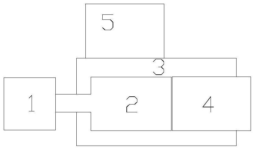
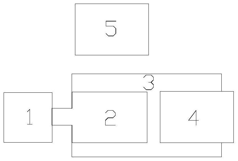
[0060] Figures 1A-1B A structural block diagram of an end effector and an end shaft assembly provided for an embodiment of the present invention; wherein, Figure 1A is the structural block diagram when the conversion unit is docked with the end effector, Figure 1B It is the structural block diagram when the conversion unit is docked with the end shaft...


PUM


Abstract

The invention provides an end effector and an end shaft assembly, a robot and a control method. The end effector and the end shaft assembly include a drive unit, a conversion unit, an end shaft, an end effector, and a braking unit; the drive unit is connected to the A conversion unit, through the conversion of the conversion unit, respectively drives the movement of the end shaft and the end effector; the end effector can be connected to the end shaft in relative motion, so that the end shaft can drive the end The actuators move synchronously; the brake unit is used to brake the end shaft when the end effector moves under the drive of the conversion unit, so that the end shaft does not follow the end effector sports. By adopting the end effector and the end shaft assembly of the present invention, by using the end effector and the end shaft assembly to share the same drive unit, the weight of the assembly itself is reduced, thereby increasing the effective load at the output end of the end effector.

Description

technical field [0001] The invention relates to the technical field of automation, in particular to an end effector and an end shaft assembly, a robot and a control method. Background technique [0002] With the development of industry and technology, robots have been widely used and developed rapidly. In the field of robots, commonly used robots can include: multi-axis robots (such as Figure 4 shown) and parallel robots (such as Figure 5 shown), the multi-axis robot and the parallel robot are located on the last axis of the robot (hereinafter referred to as the end axis) to set the end effector that can realize various functions. Usually, the driving units of the end effector and the end axis are respectively using their own driven by the drive unit. [0003] The problem with the end shaft and end effector assembly with the above structure is that since two drive units are required to drive the end shaft and the end effector respectively at the same time, the weight of t...

Claims


Application Information

Patent Timeline
Patent Type & Authority Patents(China)
IPC IPC(8): B25J15/00B25J15/02B25J15/04B25J13/00B25J9/16
Inventor 何国斌王程明李文龙
Owner ROBOTICS ROBOTICS SHENZHEN LTD
Learn More