Aircraft provided with a swiveling tail rotor, and an associated method

Active Publication Date: 2012-06-28
EUROCOPTER
View PDF8 Cites 26 Cited by
  • Summary
  • Abstract
  • Description
  • Claims
  • Application Information

AI Technical Summary

Benefits of technology

[0036]Consequently, the invention makes it possible to tilt the rotary wing towards the rear end of the aircraft in order to put the rotary wing into autorotation, thereby giving it a better fineness ratio (if the rotor is flat) and enabling the main gearbox of the rotary wing to be off-loaded. This tilt angle towards the rear enables the main gearbox to be dimensioned optimally for performing its lift function.
[0037]In addition, the latitude made available concerning the tilt angle of the main rotor towards the rear or towards the front enables moments on the drive mast of the rotary wing to be reduced, and thus makes it possible to optimize the dimensioning of the mast, insof

Problems solved by technology

The performances of a helicopter are conventionally limited by the speed of rotation of the main rotor that constitutes the rotary wing.
Thus,

Method used


Image

  • Aircraft provided with a swiveling tail rotor, and an associated method
  • Aircraft provided with a swiveling tail rotor, and an associated method
  • Aircraft provided with a swiveling tail rotor, and an associated method

Examples


Example

[0069]Elements that appear in more that one of the figures are given the same references in each of them.

DETAILED DESCRIPTION OF THE INVENTION

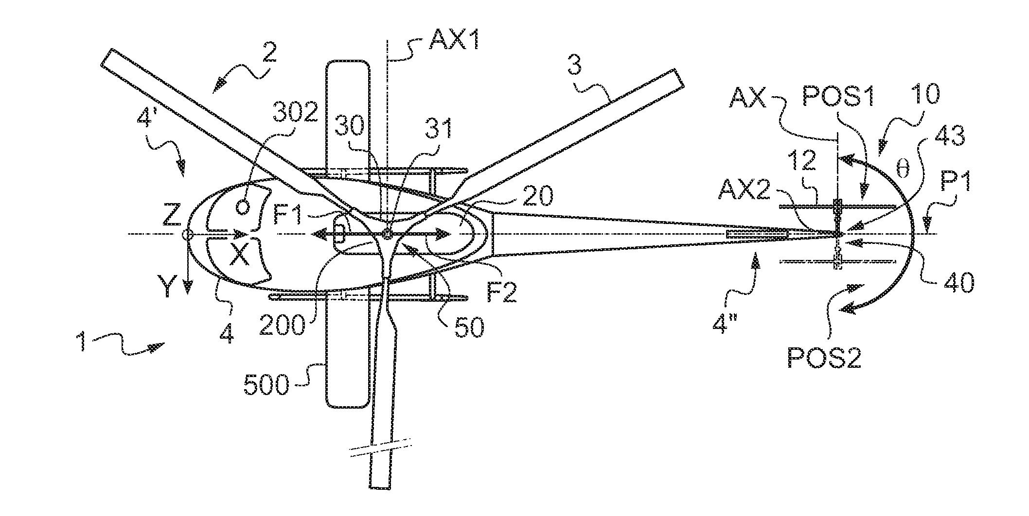
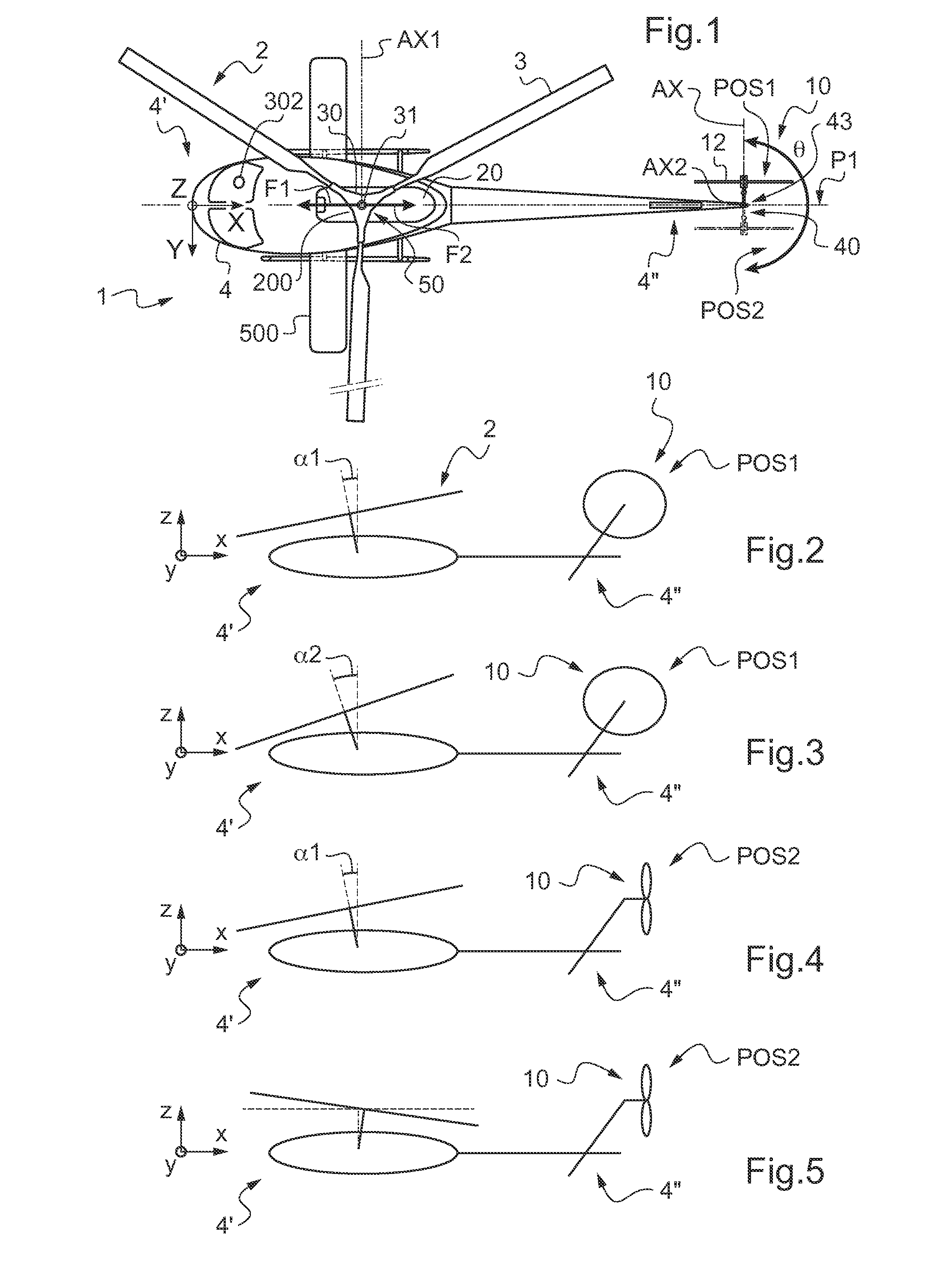
[0070]FIG. 1 is a plan view of an aircraft 1 of the invention.

[0071]Three mutually orthogonal directions referenced X, Y, and Z can be seen in FIG. 1.

[0072]The direction X represents the longitudinal axis of the aircraft shown diagrammatically, whereas another direction Y represents the transverse axis of said aircraft.

[0073]Finally, a third direction Z is referred to as the “elevation” direction and corresponds to the elevation axis of the aircraft.

[0074]FIG. 1 thus shows an aircraft 1 having an airframe 4 extending longitudinally along an anteroposterior longitudinal plane P1 of symmetry in elevation from a front end 4′ to a rear end 4″. It should be observed that the anteroposterior longitudinal plane P1 is defined by the longitudinal axis X and the elevation axis Z.

[0075]The airframe 4 carries a rotary wing 2 having a main rotor made up of...


PUM


Abstract

An aircraft (1) having an airframe (4) extending from a rear end (4″) to a front end (4′), a rotary wing (2), and a tail rotor (10). The aircraft (1) also includes a power plant (20) driving said rotary wing (2) via a main power gearbox (30) secured to a mast (31) of said rotary wing (2), said power plant (20) driving said tail rotor (10) via a tail power gearbox (40). The aircraft possesses pivot means (43) for causing the tail rotor (10) to swivel in a reversible manner from a stationary first position (POS1) towards a second position (POS2). The aircraft also includes tilt means (50) for tilting said mast (31) in a reversible manner.

Description

CROSS REFERENCE TO RELATED APPLICATION[0001]This application claims priority to French patent application no. FR 10 05016 filed on Dec. 22, 2010, the disclosure of which is incorporated in its entirety by reference herein.BACKGROUND OF THE INVENTION[0002](1) Field of the Invention[0003]The present invention relates both to a method of piloting a rotary wing aircraft having a tail rotor that is suitable for pivoting about a swivel axis, and also to such an aircraft.[0004]More particularly, the invention relates to aircraft provided firstly with a rotary wing for providing at least part of the lift of the aircraft, and secondly with a tail rotor suitable for countering the yaw torque generated by the rotary wing on the airframe of the aircraft, said tail rotor being capable of pivoting about an axis in order to contribute to propelling the aircraft.[0005](2) Description of Related Art[0006]The performances of a helicopter are conventionally limited by the speed of rotation of the main...

Claims


Application Information

Patent Timeline
IPC IPC(8): B64C27/54
CPCB64C27/82
Inventor THOMASSEY, LIONEL
Owner EUROCOPTER
Why Eureka
Try Eureka