Antenna structure and wireless communication device with antenna structure

A technology of antenna structure and radiation part, which is applied in the direction of antenna grounding switch structure connection, antenna grounding device, and devices that enable antennas to work in different bands at the same time, and can solve problems affecting antenna radiation performance, etc.

Active Publication Date: 2019-05-24
SHENZHEN FUTAIHONG PRECISION IND CO LTD +1
View PDF11 Cites 2 Cited by
  • Summary
  • Abstract
  • Description
  • Claims
  • Application Information

AI Technical Summary

Problems solved by technology

However, when an external USB device passes through the USB port, the external USB device must pass through the antenna, thereby affecting the radiation performance of the antenna

Method used


Image

  • Antenna structure and wireless communication device with antenna structure
  • Antenna structure and wireless communication device with antenna structure
  • Antenna structure and wireless communication device with antenna structure

Examples


Embodiment Construction

[0020] The following will clearly and completely describe the technical solutions in the embodiments of the present invention with reference to the accompanying drawings in the embodiments of the present invention. Obviously, the described embodiments are only some, not all, embodiments of the present invention. Based on the embodiments of the present invention, all other embodiments obtained by persons of ordinary skill in the art without making creative efforts belong to the protection scope of the present invention.

[0021] It should be noted that when an element is referred to as being "electrically connected" to another element, it may be directly on the other element or there may be an intervening element. When an element is considered to be "electrically connected" to another element, it may be connected by contact, eg, by a wire connection, or non-contact, eg, by a non-contact coupling.

[0022] Unless otherwise defined, all technical and scientific terms used herein ...


PUM


Abstract

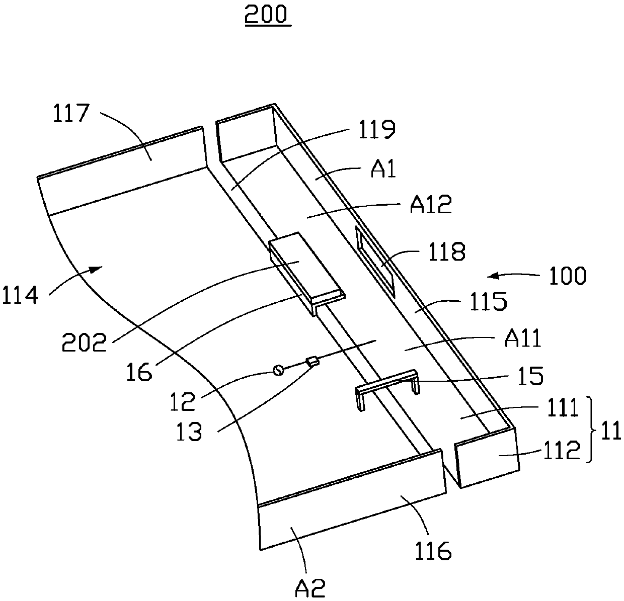
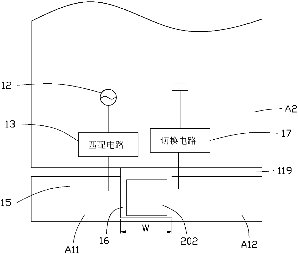
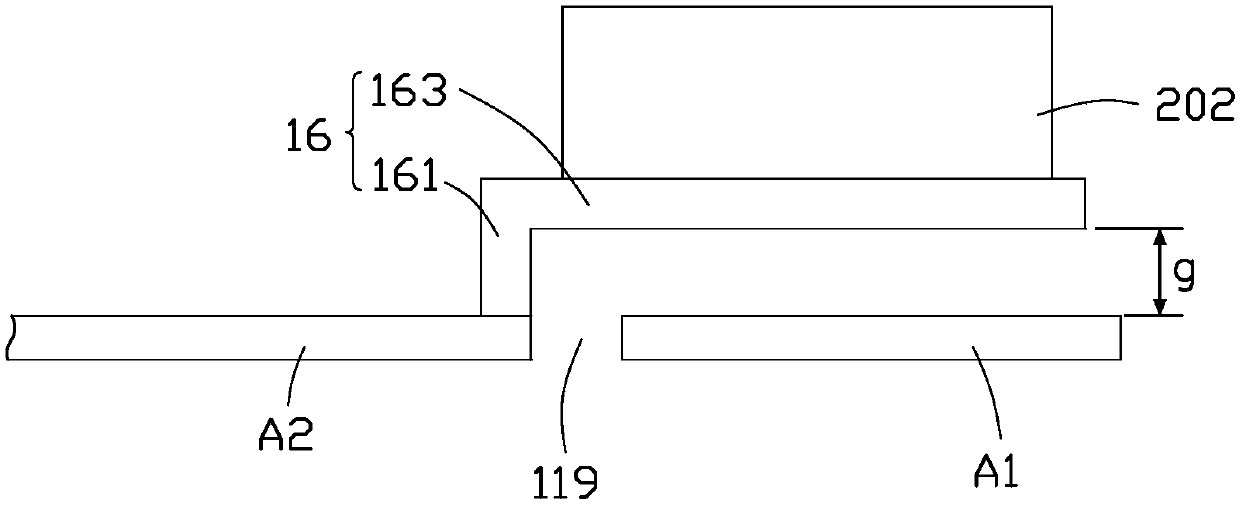
The invention provides an antenna structure, including a shell, a feed source, a connecting part and a coupling part. The shell is provided with a slot which divides the shell into a radiating part and a grounding part spaced from each other. The grounding part acts as the ground of the antenna structure. One end of the feed source is electrically connected to the radiating part to feed a currentsignal to the radiating part. One end of the connecting part is electrically connected to the radiating part, and the other end is electrically connected to the grounding part, in order to provide grounding for the radiating part. One end of the coupling part is electrically connected to the grounding part, and the other end is spaced from and coupled to the radiating part. The antenna structure can prevent the influence of electronic elements on the radiation of the antenna structure, and the arrangement of the coupling part can make the antenna structure generate an additional resonance modeto achieve a broadband effect. The invention also provides a wireless communication device with the antenna structure.

Description

technical field [0001] The invention relates to an antenna structure and a wireless communication device with the antenna structure. Background technique [0002] With the advancement of wireless communication technology, wireless communication devices are constantly developing towards a thinner and lighter trend, and consumers have higher and higher requirements for product appearance. Due to the advantages of metal shells in appearance, structural strength, heat dissipation, etc., more and more manufacturers design wireless communication devices with metal shells, such as backplanes, to meet the needs of consumers, and use metal shells As an antenna for a wireless communication device. In addition, a USB port is usually provided at the bottom of the wireless communication device, so that an external USB device is electrically connected to a USB module inside the wireless communication device through the USB port, and then charging or data transmission is performed. Howev...

Claims


Application Information

Patent Timeline
Patent Type & Authority Applications(China)
IPC IPC(8): H01Q1/52H01Q1/44H01Q1/36H01Q1/48H01Q1/50H01Q1/22
CPCH01Q1/243H01Q9/145H01Q9/42H01Q5/335H01Q13/10H01Q5/30H01Q5/50
Inventor 张子轩
Owner SHENZHEN FUTAIHONG PRECISION IND CO LTD
Why Eureka
Try Eureka