
End device with wifi MIMO antenna

A technology for terminal equipment and antennas, which is applied to antennas, antenna parts, antenna grounding devices, etc., and can solve problems such as limited efficiency

Active Publication Date: 2020-09-22
GUANGDONG OPPO MOBILE TELECOMM CORP LTD
View PDF3 Cites 0 Cited by
  • Summary
  • Abstract
  • Description
  • Claims
  • Application Information

AI Technical Summary

Problems solved by technology

However, due to the influence of the metal shield in the terminal equipment, the antenna designed in this way has limited efficiency.

Method used


Image

  • End device with wifi MIMO antenna
  • End device with wifi MIMO antenna
  • End device with wifi MIMO antenna

Examples


Embodiment Construction

[0029] The application will be further described in detail below in conjunction with the accompanying drawings and embodiments. It should be understood that the specific embodiments described here are only used to explain the present application, but not to limit the present application. In addition, it should be noted that, for the convenience of description, only some structures related to the present application are shown in the drawings but not all structures.

[0030] With the development of communication technologies, current terminal devices need to support multiple communication modes at the same time. In a scenario where a Long Term Evolution (Long Term Evolution, LTE) communication technology has been widely used, a terminal device at least needs to have an LTE antenna supporting LTE communication. Since LTE requires diversity reception technology and MIMO technology, at least two LTE antennas are required in the terminal equipment. Since the frequency band of LTE ...


PUM


Abstract

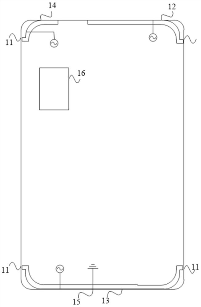
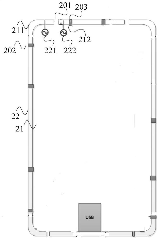
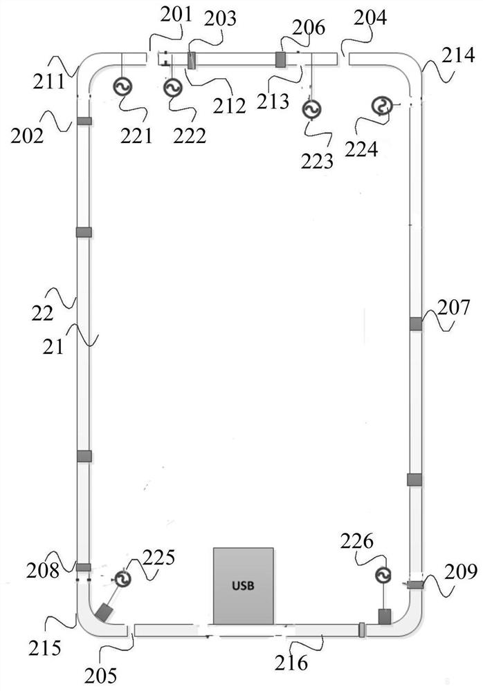
The embodiment of the invention discloses terminal equipment with a WIFI MIMO antenna. The terminal equipment comprises a terminal equipment main body, wherein the terminal equipment main body is provided with a metal frame, a first antenna branch and a second antenna branch are formed after the metal frame at two sides of a first gap of the metal frame at one side of the terminal equipment main body is connected with ground by a metal grounding piece far away from the first gap, the first antenna branch is connected with a first feeding circuit in the terminal equipment main body to form a main WIFI antenna, a working frequency band of the main WIFI antenna is between a WIFI 5GHz frequency band and a WIFI 2.4GHz frequency band, the second antenna branch is connected with a second feedingcircuit in the terminal equipment main body to form a 5GHz WIFI antenna, and a working frequency band of the 5GHz WIFI antenna is within the WIFI 5GHz frequency band. The terminal equipment with the WIFI MIMO antenna, provided by the embodiment of the invention, is used for improving the applicability of the terminal equipment on WIFI MIMO performance.

Description

technical field [0001] The embodiment of the present application relates to antenna technology, and in particular to a terminal device with a WIFI MIMO antenna. Background technique [0002] The functions of portable terminal devices such as mobile phones and tablet computers have become more and more powerful, and various functions are integrated therein. Many of these functions need to communicate with the outside world, so the terminal device also needs multiple antennas to support various functions that need to communicate with the outside world. [0003] However, under the design trend of thinner and lighter terminal equipment, it brings great difficulty to the design of many antennas. The net space of the antenna is greatly limited. How to design the required multiple antennas in the limited net space is a challenge. One of the design difficulties in terminal equipment design. [0004] Wireless fidelity (WIreless-Fidelity, WIFI) communication, as a wireless local are...

Claims


Application Information

Patent Timeline
Patent Type & Authority Patents(China)
IPC IPC(8): H01Q1/36H01Q1/48H01Q1/50H01Q1/24H01Q1/22
CPCH01Q1/2291H01Q1/243H01Q1/36H01Q1/48H01Q1/50
Inventor 吴坚林
Owner GUANGDONG OPPO MOBILE TELECOMM CORP LTD
Learn More