
Air duct structure of air conditioner and air conditioner with air duct structure

An air conditioner and air duct technology, which is applied in the air conditioner air duct structure and the air conditioner field with it, can solve the problems of large air outlet width, long air outlet distance, and inability to form long-distance air supply, and achieve wind feeling Comfortable and adjustable air supply mode

Pending Publication Date: 2019-05-31
GD MIDEA AIR-CONDITIONING EQUIP CO LTD
View PDF0 Cites 7 Cited by
  • Summary
  • Abstract
  • Description
  • Claims
  • Application Information

AI Technical Summary

Problems solved by technology

However, the existing cabinet-type air conditioners cannot take into account the design of long air outlet distance and large air outlet width. When the air outlet distance is long enough, the wind feeling is often not soft enough, and the user experience is not good; when the air outlet width is large, It is also unable to form a long-distance air supply and cannot meet the various needs of users
In addition, when the air conditioner is equipped with an integral air duct, the volume of the air duct itself is large, occupying a large space inside the fuselage, and the wind in the air duct far away from the fan is weakly driven by the fan.

Method used


Image

  • Air duct structure of air conditioner and air conditioner with air duct structure
  • Air duct structure of air conditioner and air conditioner with air duct structure
  • Air duct structure of air conditioner and air conditioner with air duct structure

Examples


Embodiment 1

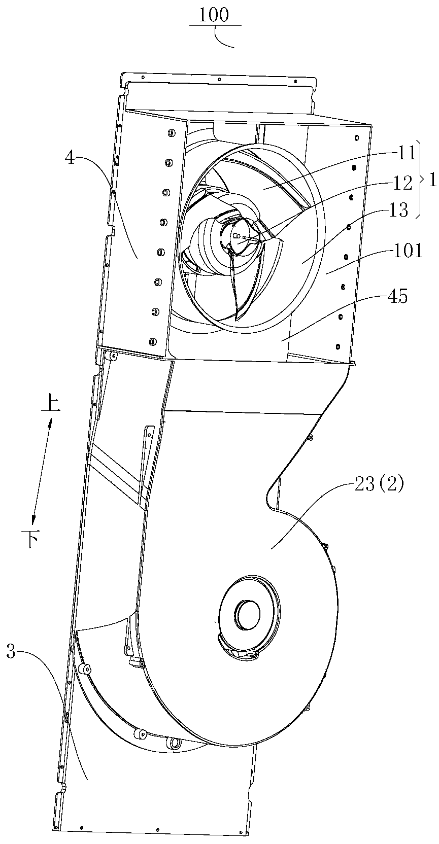
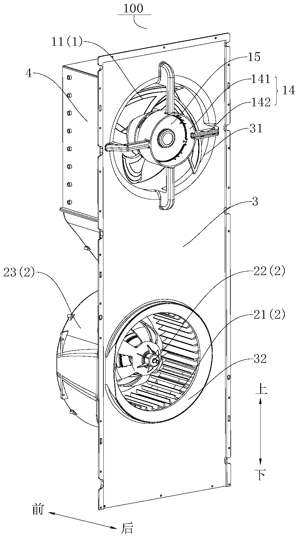
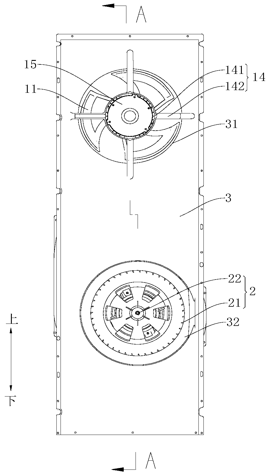
[0090] Such as figure 1 As shown, an air duct structure 100 for an air conditioner includes a fan bracket 3, a first wind wheel assembly 1, a second wind wheel assembly 2, and a wind collecting plate 4. Among them, such as figure 2 As shown, a first fan mounting hole 31 and a second fan mounting hole 32 are formed on the fan bracket 3. Such as figure 1 As shown, the first wind wheel assembly 1 is mounted on the first fan mounting hole 31, such as figure 2 As shown, the second wind wheel assembly 2 is installed on the second fan mounting hole 32. Such as Figure 4 As shown, a mixing cavity 101 is formed on the fan bracket 3 on the air outlet side of the first wind wheel 11.

[0091] Such as Figure 5 , Image 6 As shown, the first wind wheel assembly 1 includes: a first wind wheel 11, a first motor 12, a wind guide ring 13, a motor mounting frame 14 and a motor cover 15. Wherein, a motor mounting frame 14 is provided at the first fan mounting hole 31, the first motor 12 is moun...

Embodiment 2

[0097] Such as Figure 7 As shown, the cylindrical air guide ring 13 of the air conditioner air duct structure 100 in Embodiment 1 is replaced with a plurality of air guide rings 13 detachably connected in sequence along the axial direction, and the air guide ring 13 defines a mixing In the air cavity 101, an air guiding air inlet 131 is formed between the adjacent air guiding rings 13, and the air from the second wind wheel assembly 2 can enter the mixing cavity 101 through the air guiding air inlet 131 and be connected to the first air wheel The air from the component 1 is mixed and discharged. In addition, the axial flow fan in Embodiment 1 is replaced with a diagonal flow fan, and other identical structures will not be repeated. The air mixing cavity 101 of the air duct structure 100 of the air conditioner of this embodiment is located inside the air guide ring 13.

[0098] Such as Picture 9 As shown, the air conditioner 1000 having the air duct structure 100 of the air con...


PUM


Abstract

The invention discloses an air duct structure of an air conditioner and the air conditioner with the air duct structure. The air duct structure of the air conditioner comprises a draught fan support,a first wind wheel assembly and a second wind wheel assembly. A first draught fan mounting hole and a second draught fan mounting hole are formed in the draught fan support. The first wind wheel assembly comprises a first wind wheel mounted at the position of the first draught fan mounting hole, and an air mixing cavity is formed in the position, located on the air outflow side of the first wind wheel, of the draught fan support. The second air wheel assembly comprises a second wind wheel mounted at the position of the second draught fan mounting hole, an included angle is formed between the air inflow direction of the second wind wheel and the air outflow direction of the second wind wheel, the second wind wheel supplies air towards the first wind wheel, and when the first wind wheel andthe second wind wheel simultaneously work, outflow air of the second wind wheel and outflow air of the first wind wheel are mixed in the air mixing cavity for air outflow. According to the air duct structure of the air conditioner in the embodiment, after the outflow air of the second wind wheel and the outflow air of the first wind wheel are mixed in the air mixing cavity, the mixed air is delivered outwards, the air feeling of the outflow air is comfortable, and the air supply distance is long.

Description

Technical field [0001] The invention belongs to the technical field of air conditioners, in particular to an air duct structure of an air conditioner and an air conditioner with the same. Background technique [0002] The cabinet air conditioner includes a casing, heat exchange parts, air duct parts, air outlet frame parts, etc. The air duct parts are mainly used to guide the heat exchanged air to the air outlet and send air outward. However, the existing cabinet-type air conditioners cannot take into account the design of long air outlet distance and large air outlet width. When the air outlet distance is far enough, the wind feeling is often not soft enough and the user experience is poor; when the air outlet width is large, It cannot form a long-distance air supply and cannot meet the various needs of users. In addition, when the air conditioner is provided with an integral air duct, the air duct itself has a large volume and occupies a large space inside the fuselage, and th...

Claims


Application Information

Patent Timeline
Patent Type & Authority Applications(China)
IPC IPC(8): F24F1/0018F24F1/0033F24F1/0059F24F13/04
Inventor 钟志尧程超彭杰林乔德山宫笋
Owner GD MIDEA AIR-CONDITIONING EQUIP CO LTD
Learn More