Automatic emergency syringe

A syringe and automatic technology, applied in the field of syringes, can solve the problems of complex operation, long waste of time, difficult disinfection, etc., and achieve the effect of ensuring hygiene and safety

Active Publication Date: 2012-08-01
INST OF PHARMACOLOGY & TOXICOLOGY ACAD OF MILITARY MEDICAL SCI P L A
View PDF3 Cites 5 Cited by
  • Summary
  • Abstract
  • Description
  • Claims
  • Application Information

AI Technical Summary

Problems solved by technology

[0002] At present, in my country's medical device market, there are many types of syringes, which can be simply divided into four generations of syringes in the form of syringes: (1) The first generation of syringes is made of all glass, used many times in hospitals, and repeatedly cooked under high temperature and high pressure , prone to cross-infection, complicated to use in first aid and self-rescue, unsafe and inconvenient to use, currently only underdeveloped countries in Africa and other places are still using it
(2) The second generation of syringes is the disposable plastic syringes commonly used in China. In normal use, it requires a high degree of aseptic operation, complex operations, high work intensity, low efficiency, easy cross-infection, and valuable drug residues. large
However, there are some problems in the auto-injectors currently on the market: (1) structurally, the structure of some auto-injectors is too complicated and the number of parts will inevitably lead to a decline in the reliability and safety of the device, and when adapting to vibration, extrusion, etc. There are deficiencies in pressure, collision, etc.
(2) In terms of appearance, some automatic in...

Method used


Image

  • Automatic emergency syringe
  • Automatic emergency syringe
  • Automatic emergency syringe

Examples


Embodiment Construction

[0026] The specific embodiments of the present invention will be described in detail below with reference to the accompanying drawings. The specific embodiments in the specification are preferred technical solutions of the present invention, and do not constitute limitations to the present invention.

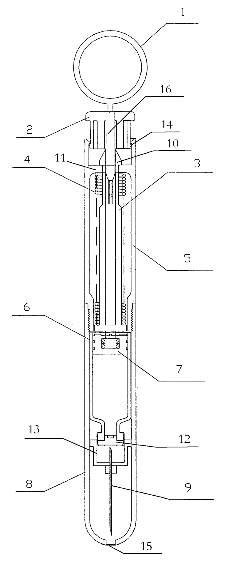
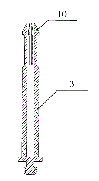
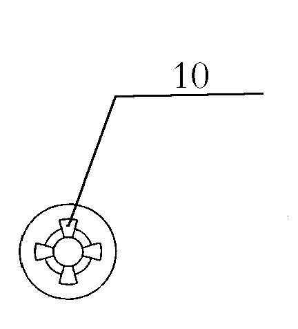
[0027] figure 1 It is a schematic diagram of the internal structure of the automatic emergency injector according to the present invention. Wherein, the automatic emergency syringe generally includes a firing part and a drug-loading part, the firing part has a safety pull ring 1, a firing device 2, an ejection rod 3, a spring 4, and an upper cylinder body 5, and the drug-loading part has a liquid cartridge 6. Piston 7, lower cylinder 8 and injection needle 9. The safety pull ring 1 is inserted in the firing device 2, and is used to prevent the false shooting of the firing device 2 from firing. An inner ring 11 is arranged inside the upper cylinder body 5 , and the inner ring 1...


PUM


Abstract

The invention provides an automatic emergency syringe, which comprises a percussion portion and a drug loading portion. The percussion portion is provided with a percussion unit (2), an ejector bar (3), a spring (4) and an upper tube (5). The drug loading portion is provided with a liquor tube (6), a piston (7), a lower tube (8) and an injection needle (9). The percussion unit (2) is held at the top of the upper tube (5). A plurality of jaws (10) are arranged at the upper end of the ejector bar (3). The upper end of each jaw (10) is abutted to the percussion unit (2), and the lower end of each jaw (10) is abutted to the upper surface of an inner ring (11) inside the upper tube (3). The spring (4) is wound around the ejector bar (3) and is compressed. The upper end of the spring (4) is abutted to the lower surface of the inner ring (11). The liquor tube (6) containing liquor is disposed inside the lower tube (8). A rubber plug (7) is disposed at the lower end of the liquor tube (6). The piston (7) is disposed at the upper end of the liquor tube (6). The lower end of the ejector bar (3) is inserted into the piston (7). The injection needle (9) is disposed inside the lower tube (8) and on the lower portion of the rubber plug (12) inside the liquor tube (6). The automatic emergency syringe is suitable for emergency treatment, can be used for self-rescue, and is reasonable in structure and safe and convenient in use.

Description

technical field [0001] The invention relates to a syringe, more specifically to an automatic emergency syringe suitable for field first aid, field work and home first aid and capable of self-rescue. Background technique [0002] At present, in my country's medical device market, there are many types of syringes, which can be simply divided into four generations of syringes in the form of syringes: (1) The first generation of syringes is made of all glass, used many times in hospitals, and repeatedly cooked at high temperature and high pressure , easy to produce cross-infection, it is also very complicated to use in first aid and self-rescue, and it is not safe and inconvenient to use. At present, only underdeveloped countries such as Africa are still using it. (2) The second generation of syringes is the disposable plastic syringes commonly used in China at present. When used in normal times, it requires a high degree of aseptic operation, complicated operations, high work in...

Claims


Application Information

Patent Timeline
IPC IPC(8): A61M5/20A61M5/31A61M5/32
Inventor 梅兴国孙思平龚伟李志平郭庆东
Owner INST OF PHARMACOLOGY & TOXICOLOGY ACAD OF MILITARY MEDICAL SCI P L A
Why Eureka
Try Eureka