Connecter of flexible inhaul cable offset rod part

A technology of flexible cables and connectors, which is applied in the direction of building components, building reinforcements, structural elements, etc., can solve the problems of large space required for connectors, undetectable, and unclear acceptance standards, so as to promote overall improvement and development, Inspection and acceptance clear and convenient effect

Pending Publication Date: 2019-06-04
SHANGHAI YIPINLILIAN CONSTR TECH CO LTD
View PDF0 Cites 0 Cited by
  • Summary
  • Abstract
  • Description
  • Claims
  • Application Information

AI Technical Summary

Problems solved by technology

[0002] The current prefabricated structure has become a new industry nationwide, but whether the connection to the prefabricated structure is safe and reliable, whether the prefabricated structure has actually improved efficiency, whether it has really accelerated the speed, to what extent it has improved the environment, etc. However, there are many controversies; in the assembly process of prefabricated structures, it is inevitable that the ordinary steel bars, prestressed steel bars and other rods fixed on the two butt joints will have deviations within the allowable range during the butt joint. In order to adapt to this butt joint At present, grouting sleeve connection, anchor grout lap connection and other methods are mostly used. These connection methods have disadvantages such as complicated construction technology, undetectable, unclear acceptance standards, and long waiting time to reach strength.
[0003] Another way of connecting rods such as steel bars is to use bolted connections, but bolted connections not only significantly weaken the section of the member, but also require a fixed angle of wrench rotation for bolt tightening, which requires a large space for the connecting piece
[0004] As there is no reliable and convenient connection method between steel bars and prestressed tendons of prefabricated components, the current prefabricated structure has been greatly restricted and questioned, and the assembly rate is difficult to further improve

Method used


Image

  • Connecter of flexible inhaul cable offset rod part
  • Connecter of flexible inhaul cable offset rod part
  • Connecter of flexible inhaul cable offset rod part

Examples


Embodiment 1

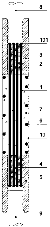
[0024] Such as figure 1 As shown, an embodiment of the present invention comprises a flexible stay cable 1, a first anchor head 2 of a stay cable, a first threaded sleeve 3, a second anchor head 4 of a stay cable, a second threaded sleeve 5, a spiral steel bar 6 and High-strength cement-based grouting material 7.

[0025] The first cable anchor head 2 and the cable second anchor head 4 respectively anchor the two ends of the flexible cable 1, and the flexible cable 1 is a plurality of separated high-strength tension filaments.

[0026] The first threaded sleeve 3 anchors the first anchor head 2 of the first anchor head 2 of the rod member 8 and the dragline respectively with a threaded pair.

[0027] The second threaded sleeve 5 anchors the rod part two 9 and the second anchor head 4 of the dragline respectively with a threaded pair.

[0028] The spiral steel bar 6 is arranged around the flexible cable 1; a cavity 10 is set in the area where the spiral steel bar 6 is located...

Embodiment 2

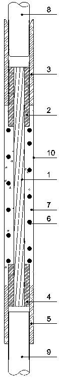
[0030] Such as figure 2 As shown, another embodiment of the present invention includes a flexible cable 1, a first anchor head 2 of the cable, a first threaded sleeve 3, a second anchor head 4 of the cable, a second threaded sleeve 5, and a spiral steel bar 6 And high-strength cement-based grouting material7.

[0031] The first anchor head 2 of the cable and the second anchor head 4 of the cable anchor the two ends of the flexible cable 1 respectively;

[0032] The first threaded sleeve 3 anchors the first anchor head 2 of the first anchor head 2 of the rod member 8 and the dragline respectively with a threaded pair.

[0033] The second threaded sleeve 5 anchors the rod part two 9 and the second anchor head 4 of the dragline respectively with a threaded pair.

[0034] The spiral steel bar 6 is arranged around the flexible cable 1; a cavity 10 is set in the area where the spiral steel bar 6 is located inside the prefabricated component, and the high-strength cement-based gro...

Embodiment 3

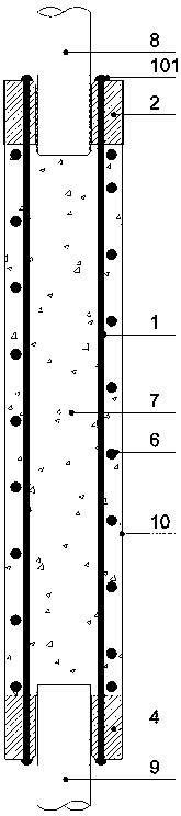
[0036] Such as image 3 As shown, another embodiment of the present invention includes a flexible cable 1 , a first anchor head 2 of the cable, a second anchor head 4 of the cable, a spiral steel bar 6 and a high-strength cement-based grouting material 7 .

[0037] The first anchor head 2 of the cable and the second anchor head 4 of the cable respectively anchor the two ends of the flexible cable 1; 8 and the periphery of rod part 2 9; the first anchor head 2 of the stay cable is a radial elastic nut with serrated threads.

[0038] The spiral steel bar 6 is arranged around the flexible cable 1; a cavity 10 is set in the area where the spiral steel bar 6 is located inside the prefabricated component, and the high-strength cement-based grouting material 7 is poured into the cavity 10 .


PUM


Abstract

The invention discloses a connecter of a flexible inhaul cable offset rod part to connect an offset rod part one and an offset rod part two pre-embedded in two prefabricated parts. The connector comprises flexible inhaul cables, an inhaul cable first anchor head, first threaded sleeve tubes, an inhaul cable second anchor head, second threaded sleeve tubes, spiral reinforcements and a high slurry body; the inhaul cable first anchor head and the inhaul cable second anchor head are separately anchored at the two ends of the flexible inhaul cables, the rod part one and the inhaul cable first anchor head are separately anchored by the first threaded sleeve tubes through threaded pairs, the rod part two and the inhaul cable second anchor head are separately anchored by the second threaded sleevetubes through threaded pairs, and the spiral reinforcements are arranged around the flexible inhaul cables in a encircled mode; the high slurry body is poured into the cavity body formed by the encirclement of the spiral reinforcements, and the spiral reinforcements strengthen the anti-resistance capability of the high slurry body column. The connecter of flexible inhaul cable offset rod part issmall in size, save in material use, suitable for butting bars with a large tolerance, convenient in detection and test, and clear in acceptance standard.

Description

technical field [0001] The invention relates to the technical field of connection of assembled structures, in particular to a flexible cable deflection rod connector. Background technique [0002] The current prefabricated structure has become a new industry nationwide, but whether the connection to the prefabricated structure is safe and reliable, whether the prefabricated structure has actually improved efficiency, whether it has really accelerated the speed, to what extent it has improved the environment, etc. However, there are many controversies; in the assembly process of prefabricated structures, it is inevitable that the ordinary steel bars, prestressed steel bars and other rods fixed on the two butt joints will have deviations within the allowable range during the butt joint. In order to adapt to this butt joint At present, grouting sleeve connection, anchor grout lap connection and other methods are mostly used. These connection methods have disadvantages such as c...

Claims


Application Information

Patent Timeline
Patent Type & Authority Applications(China)
IPC IPC(8): E04C5/16
Inventor 郭卓明
Owner SHANGHAI YIPINLILIAN CONSTR TECH CO LTD
Why Eureka
Try Eureka