Elastic sleeve rod piece connector

An elastic sleeve and connector technology, which is applied to building components, building reinforcements, structural elements, etc., can solve the problems of insufficient direct force, complicated installation and tightening, and large space for angle steel. Wide range of occasions, small overall length effect

Inactive Publication Date: 2019-07-05
SHANGHAI YIPINLILIAN CONSTR TECH CO LTD
View PDF0 Cites 0 Cited by
  • Summary
  • Abstract
  • Description
  • Claims
  • Application Information

AI Technical Summary

Problems solved by technology

[0004] For example, the prefabricated steel bar connection structure of the famous Finnish Peikko company pre-embeds an angle steel with an end face, and then fixes one side of the steel bar on the angle steel by welding, and at the same time opens a hole on the end face, and then passes the other side of the steel bar through it. The end face is connected with bolts; although this method also realizes the connection with deviation of the butt joints, the angle steel used takes up a lot of space, the force is not direct enough, and when the number of butt steel bars is large, the installation and installation of the angle steel and bolts are difficult. Tightening is relatively complicated, so it is difficult to promote in a large area, and it is only used in the connection of small square columns in industrial plants.

Method used


Image

  • Elastic sleeve rod piece connector
  • Elastic sleeve rod piece connector
  • Elastic sleeve rod piece connector

Examples


Embodiment 1

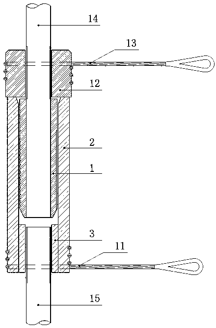
[0062] Such as Figure 1~Figure 4 As shown, a specific embodiment of the present invention includes a slit waist drum type threaded inner sleeve 1-1, a first outer sleeve 2, an anchor plate 3 at the end of the first outer sleeve, a first flexible tension member 11, and a pressure nut 12 And the second flexible tension member 13.

[0063] The first outer casing end anchor plate 3 is arranged on one end of the first outer casing 2 and is connected with a thread pair, and the inner side of the other end of the first outer casing 2 is provided with a flared tapered surface; the first outer casing end anchor plate 3 is connected to the second rod 15 . The elastic inner sleeve 1 is arranged at the end of the first rod 14 and connected with a threaded pair.

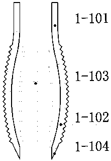
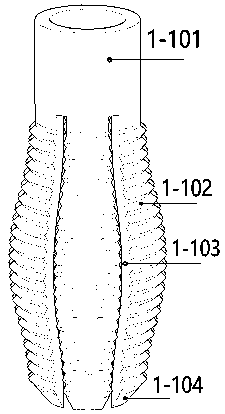
[0064] The elastic inner sleeve 1 is a slit waist drum type thread inner sleeve 1-1, and the slotted waist drum type thread inner sleeve 1-1 includes a straight thread sleeve 1-101 at the head of the inner sleeve, and a convex ...

Embodiment 2

[0069] Such as figure 1 , Figure 5~7 As shown, another specific embodiment of the present invention includes a slit umbrella threaded inner casing 1-2, a first outer casing 2, an anchor plate 3 at the end of the first outer casing, a first flexible tension member 11, and a pressure nut 12 and the second flexible tension member 13.

[0070] The first outer casing end anchor plate 3 is arranged on one end of the first outer casing 2 and is connected with a thread pair, and the inner side of the other end of the first outer casing 2 is provided with a flared tapered surface; the first outer casing end anchor plate 3 is connected to the second rod 15 . The elastic inner sleeve 1 is arranged at the end of the first rod 14 and connected with a threaded pair.

[0071] The slotted umbrella-shaped threaded inner casing 1-2 includes the straight threaded casing 1-201 at the head of the inner casing, the umbrella-shaped threaded casing 1-202 at the tail of the inner casing and multipl...

Embodiment 3

[0077] Such as figure 1 , Figure 8~11 As shown, another specific embodiment of the present invention comprises a serrated thread elastic composite sleeve 1-3, a first outer sleeve 2, an anchor plate 3 at the end of the first outer sleeve, a first flexible tension member 11, a pressure nut 12 and The second flexible tension member 13 .

[0078] The first outer casing end anchor plate 3 is arranged on one end of the first outer casing 2 and is connected with a thread pair, and the inner side of the other end of the first outer casing 2 is provided with a flared tapered surface; the first outer casing end anchor plate 3 is connected to the second rod 15 . The elastic inner sleeve 1 is arranged at the end of the first rod 14 and connected with a threaded pair.

[0079] The sawtooth thread elastic combination sleeve 1-3 includes a slotted inner sleeve 1-301 and an elastic sawtooth thread ring 1-302.

[0080] A plurality of circumferential grooves 1-303 are arranged on the outer...


PUM


Abstract

The invention provides an elastic sleeve rod piece connector, which comprises an elastic inner sleeve, an outer sleeve, an outer sleeve end anchor plate, a first flexible tension piece, a pressure bearing nut and a second flexible tension piece. The outer sleeve end anchor plate is arranged at one end of the outer sleeve and connected with one end of the outer sleeve through a thread pair; the outer sleeve end anchor plate is connected with a second rod piece, the elastic inner sleeve is anchored with the outer sleeve, and the elastic inner sleeve is connected with a first rod piece through athread pair; and the first flexible tension piece is arranged on the outer side of the outer sleeve, the end of the first rod piece is provided with the pressure bearing nut, and the second flexible tension piece is arranged on the outer side of the pressure bearing nut. According to the elastic sleeve rod piece connector, the size is small, adopted materials are saved, the construction speed is high, inspection is convenient, and the acceptance standard is definite.

Description

technical field [0001] The invention relates to the technical field of connection of structures, in particular to an elastic sleeve rod connector. Background technique [0002] In engineering construction, it is unavoidable that ordinary steel bars, prestressed steel bars, and other rods fixed on two assembly members have deviations within the allowable range when they are connected. , corrugated pipe reserved hole grouting connection and the use of connection boxes, etc. These connection methods have disadvantages such as complicated construction technology, undetectable quality, difficult to guarantee quality, and long waiting time to reach strength. If direct connection methods such as straight threaded connections are used , the positioning and manufacturing accuracy of the connecting rods are extremely demanding, and the error of half the pitch in the axial direction is an insurmountable obstacle. [0003] The bolt connection must be tightened to realize the complete c...

Claims


Application Information

Patent Timeline
Patent Type & Authority Applications(China)
IPC IPC(8): E04C5/16
CPCE04C5/165
Inventor 郭卓明
Owner SHANGHAI YIPINLILIAN CONSTR TECH CO LTD
Why Eureka
Try Eureka