
Elastic firing pin alignment assembling type rod piece connector

A connector and elastic technology, applied in the direction of building components, building reinforcements, structural elements, etc., can solve the problems of insufficient direct force, large space occupied by angle steel, inconvenient transportation and installation, etc., reducing material consumption and reducing overall length. , The effect of a wide range of applications

Inactive Publication Date: 2019-06-21
SHANGHAI YIPINLILIAN CONSTR TECH CO LTD
View PDF0 Cites 0 Cited by
  • Summary
  • Abstract
  • Description
  • Claims
  • Application Information

AI Technical Summary

Problems solved by technology

[0004] For example, the prefabricated steel bar connection structure of the famous Finnish Peikko company pre-embeds an angle steel with an end face, and then fixes one side of the steel bar on the angle steel by welding, and at the same time opens a hole on the end face, and then passes the other side of the steel bar through it. The end face is connected with bolts; although this method also realizes the connection with deviation of the butt joints, the angle steel used takes up a lot of space, the force is not direct enough, and when the number of butt steel bars is large, the installation and installation of the angle steel and bolts are difficult. Tightening is relatively complicated, so it is difficult to promote in a large area, and it is only used in the connection of small square columns in industrial plants.
[0005] In particular, all current prefabricated assembly structures have two male and female joints for connecting rods, and the rods of the male and female joints protrude from the prefabricated components, which brings great inconvenience to transportation and installation.

Method used


Image

  • Elastic firing pin alignment assembling type rod piece connector
  • Elastic firing pin alignment assembling type rod piece connector
  • Elastic firing pin alignment assembling type rod piece connector

Examples


Embodiment 1

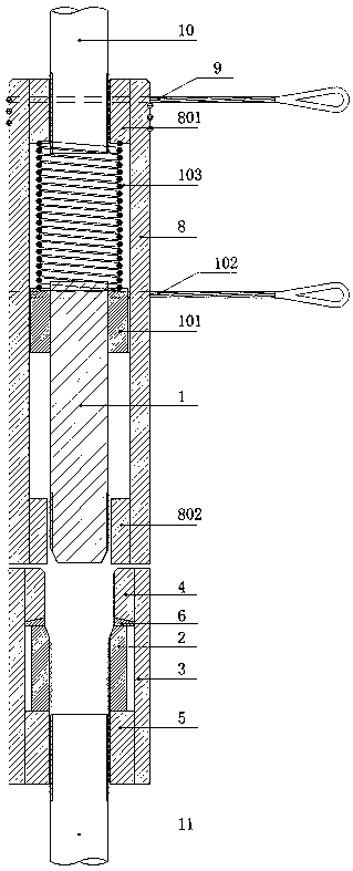
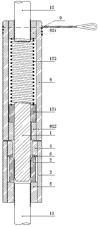
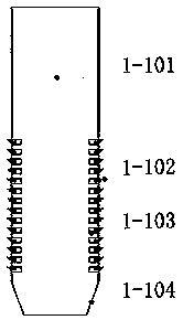
[0068] Such as Figure 1~Figure 4 As shown, a specific embodiment of the present invention includes a serrated thread elastic combined connecting shaft 1-1, a connecting shaft nut 101, a fixing pin 102, an elastic body 103, an inner casing 2, an outer casing 3, and a first end anchor plate 4 , the second end anchor plate 5 , the spherical gasket 6 , the second connection sleeve 8 , the third end anchor plate 801 , the fourth end anchor plate 802 and the first flexible tension member 9 .

[0069] The first end anchor plate 4 and the second end anchor plate 5 are respectively arranged at both ends of the outer casing 3 and connected by thread pairs.

[0070] The inner casing 2 is arranged in the outer casing 3, the outer diameter of the inner casing 2 is smaller than the inner diameter of the outer casing 3, the first end anchor plate 4 and the second end anchor plate 5 are arranged at both ends of the inner casing 2, the first end anchor plate A spherical gasket 6 is set betwe...

Embodiment 2

[0079] Such as Figure 1~2 , Figure 5~6 As shown, another specific embodiment of the present invention includes a tapered thread elastic combination connecting shaft 1-2, a connecting shaft nut 101, a fixing pin 102, an elastic body 103, an inner sleeve 2, an outer sleeve 3, and a first end anchor Plate 4 , second end anchor plate 5 , spherical washer 6 , second connecting sleeve 8 , third end anchor plate 801 , fourth end anchor plate 802 and first flexible tension member 9 .

[0080] The first end anchor plate 4 and the second end anchor plate 5 are respectively arranged at both ends of the outer casing 3 and connected by thread pairs.

[0081] The inner casing 2 is arranged in the outer casing 3, the outer diameter of the inner casing 2 is smaller than the inner diameter of the outer casing 3, the first end anchor plate 4 and the second end anchor plate 5 are arranged at both ends of the inner casing 2, the first end anchor plate A spherical gasket 6 is set between 4 and...

Embodiment 3

[0090] Such as Figure 1~2 , Figure 7~8 As shown, another specific embodiment of the present invention includes a wolf tooth connecting shaft 1-3, a connecting shaft nut 101, a fixing pin 102, an elastic body 103, an inner casing 2, an outer casing 3, a first end anchor plate 4, The second end anchor plate 5 , the spherical washer 6 , the second connecting sleeve 8 , the third end anchor plate 801 , the fourth end anchor plate 802 and the first flexible tension member 9 .

[0091] The first end anchor plate 4 and the second end anchor plate 5 are respectively arranged at both ends of the outer casing 3 and connected by screw threads.

[0092] The inner casing 2 is arranged in the outer casing 3, the outer diameter of the inner casing 2 is smaller than the inner diameter of the outer casing 3, the first end anchor plate 4 and the second end anchor plate 5 are arranged at both ends of the inner casing 2, the first end anchor plate A spherical gasket 6 is set between 4 and the...


PUM


Abstract

The invention discloses an elastic firing pin alignment assembling type rod piece connector. The connector comprises a connecting shaft, a connecting shaft nut, a fixing pin, an elastomer, an inner sleeve, an outer sleeve, a first end anchor plate, a second end anchor plate, a spherical gasket, a second connecting sleeve, a third end anchor plate, a fourth end anchor plate and a first flexible tension member; the inner sleeve, the spherical gasket, the outer sleeve, the first end anchor plate and the second end anchor plate form a first anchoring sleeve; the second connecting sleeve, the thirdend anchor plate and the fourth end anchor plate form a second anchoring sleeve; the connecting shaft, the connecting shaft nut, the fixing pin and the elastomer form an elastic connecting firing pin, and the elastic firing pin is connected to the first anchoring sleeve and the second anchoring sleeve; the first anchoring sleeve is connected to a rod piece II; and the second anchoring sleeve is connected to a rod piece I. According to the connector, the alignment butt joint of the rod pieces in an assembly structure is realized, the detection and inspection are facilitated, and the acceptancestandard is clear and definite.

Description

technical field [0001] The invention relates to the technical field of connection of structures, in particular to an elastic striker snap-fit ​​bar connector. Background technique [0002] In engineering construction, it is unavoidable that ordinary steel bars, prestressed steel bars, and other rods fixed on two assembly members have deviations within the allowable range when they are connected. , corrugated pipe reserved hole grouting connection and the use of connection boxes, etc. These connection methods have disadvantages such as complicated construction technology, undetectable quality, difficult to guarantee quality, and long waiting time to reach strength. If direct connection methods such as straight threaded connections are used , the positioning and manufacturing accuracy of the connecting rods are extremely demanding, and the error of half the pitch in the axial direction is an insurmountable obstacle. [0003] The bolt connection must be tightened to realize th...

Claims


Application Information

Patent Timeline
Patent Type & Authority Applications(China)
IPC IPC(8): E04C5/16E04B1/58
Inventor 郭卓明
Owner SHANGHAI YIPINLILIAN CONSTR TECH CO LTD
Learn More