Fan-shaped combined type material conveying support

A combined and fan-shaped technology, applied in the field of material transfer brackets, can solve the problems of increased cost, waste, redundant material transfer lines, etc., and achieve the effect of avoiding potential safety hazards.

Active Publication Date: 2019-06-07
江苏富联通讯技术股份有限公司
View PDF7 Cites 0 Cited by
  • Summary
  • Abstract
  • Description
  • Claims
  • Application Information

AI Technical Summary

Problems solved by technology

[0002] In the prior art, the material transfer bracket is often formed in the form of a square or a rectangle. While realizing the transfer and transmission of materials, the material transfer line is often lengthy, and when there is a corner material transfer requirement, the actual size of the corner cannot be adjusted. and direction to provide the best reversing material transfer bracket, it is often necessary to design the reversing material transfer bracket according to the actual size and direction of the corner, and after the actual size and direction of the other corner change next time, the original reversing material transfer bracket Can no longer be used, resulting in increased costs and waste

Method used


Image

  • Fan-shaped combined type material conveying support
  • Fan-shaped combined type material conveying support
  • Fan-shaped combined type material conveying support

Examples


Embodiment Construction

[0023] The present invention is described in further detail now in conjunction with accompanying drawing. These drawings are all simplified schematic diagrams, which only illustrate the basic structure of the present invention in a schematic manner, so they only show the configurations related to the present invention.

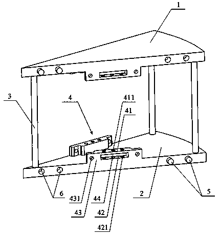
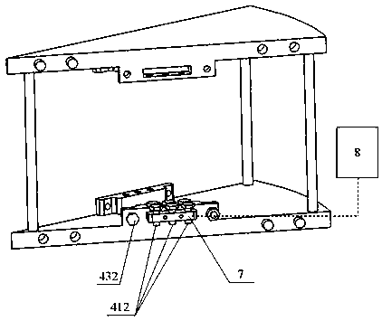
[0024] like Figure 1-4 As shown, a fan-shaped combined material transfer support includes an upper fan-shaped plate body 1, a lower fan-shaped plate body 2, and several support columns 3 between the upper fan-shaped plate body 1 and the lower fan-shaped plate body 2. At the center of both sides of the lower surface of the board body 1 and near the fan-shaped side, and at the center of both sides of the upper surface of the lower fan-shaped board 2 and near the fan-shaped side, a mounting mechanism 4 is respectively provided; the mounting mechanism 4 includes an upper installation. Plate 41, a rectangular groove 44 is provided below the upper mounting plate 4...


PUM


Abstract

The invention relates to a fan-shaped combined type material conveying support. The material conveying support is characterized by comprising an upper fan-shaped plate body (1), a lower fan-shaped plate body (2) and a plurality of supporting columns (3), the supporting columns (3) are arranged between the upper fan-shaped plate body (1) and the lower fan-shaped plate body (2); at the centers of the two sides of the lower surface of the upper fan-shaped plate body and close to the fan-shaped edges; mounting mechanisms are respectively arranged at the centers of the two sides of the upper surface of the lower fan-shaped plate body and close to the fan-shaped edges; the positions, close to the fan-shaped edges, of the two sides of the lower surface of the upper fan-shaped plate body (2), andthe positions, close to the fan-shaped edges, of the two sides of the upper surface of the lower fan-shaped plate body (2) are respectively arranged with mounting mechanisms (4). According to the fan-shaped combined type material conveying support, the defect that the cost is increased and the waste is caused due to the fact that the special reversing material transferring support needs to be independently arranged according to the size of the corner at each corner position is avoided; and the change of different corner position directions can be realized by combining different numbers of thefan-shaped combined type material conveying brackets according to the actual size of the corners.

Description

technical field [0001] The invention relates to a material transfer bracket, in particular to a fan-shaped combined material transfer bracket. Background technique [0002] In the prior art, the material transfer bracket is often formed in the form of a square or a rectangle. While realizing the transfer and transmission of materials, the material transfer line is often lengthy, and when there is a corner material transfer requirement, the actual size of the corner cannot be adjusted. and direction to provide the best reversing material transfer bracket, it is often necessary to design the reversing material transfer bracket according to the actual size and direction of the corner, and after the actual size and direction of the other corner change next time, the original reversing material transfer bracket Can no longer be used again, thereby cause cost increase, cause waste. Therefore, there is an urgent need to provide a combined material transfer bracket that can change ...

Claims


Application Information

Patent Timeline
Patent Type & Authority Applications(China)
IPC IPC(8): B65G47/64B65G47/24
Inventor 张金国
Owner 江苏富联通讯技术股份有限公司
Why Eureka
Try Eureka