A prestressed steel strand anchoring device

A technology of prestressed steel strands and anchoring devices, which is applied in the direction of buildings, building reinforcements, building components, etc. It can solve the problems of small unsuitable construction conditions, affecting the appearance of buildings, construction difficulty and high risk factor, and achieves safety and is easier to guarantee , The power transmission path is obvious, and the effect of avoiding high-altitude operations

Active Publication Date: 2021-03-12
广东庆余堂建筑科技有限公司
View PDF10 Cites 0 Cited by
  • Summary
  • Abstract
  • Description
  • Claims
  • Application Information

AI Technical Summary

Problems solved by technology

[0002] In the construction industry, the anchorage end of the steel strand is generally anchored on the side of the structural joint of the building or on the side of the outer wall of the building. On the side of the outer wall of the building, two anchoring methods are usually used: anchoring on the outside of the side span beam or using the end anchoring on the end of the beam itself. When the prestressed steel strand is anchored on the outside of the building, the anchor will be higher than the outside of the building. The decoration layer of the wall will affect the appearance of the building. When the prestressed steel strand is anchored on the outside of the building, when the construction floor is high, it is necessary to set up an outer frame, and work at high altitude. The construction difficulty and risk factor are high. Water drilling is required, and wet work is required on site. When anchored to the end of the beam itself, the stress point is on the reinforced beam itself, and the structural force transmission path is vague

Method used


Image

  • A prestressed steel strand anchoring device

Examples


Embodiment Construction

[0017] The principles and features of the present invention are described below in conjunction with the accompanying drawings, and the examples given are only used to explain the present invention, and are not intended to limit the scope of the present invention. It should be noted that the following "first" and "second" are used for descriptive purposes only, and should not be understood as indicating or implying relative importance or implicitly indicating the quantity of indicated technical features. Thus, a feature defined as "first" or "second" may explicitly or implicitly include one or more of these features.

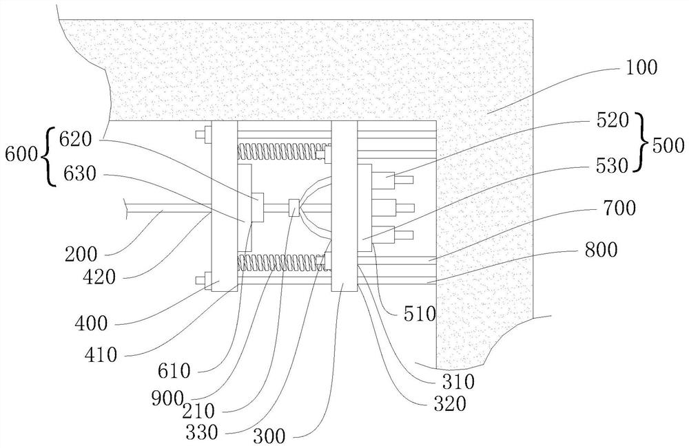
[0018] combined with figure 1 As shown, a prestressed steel strand anchoring device includes a fixed wall 100, a prestressed steel strand 200, a first steel plate 300, a second steel plate 400, a first anchor 500, a second anchor 600, a first high-strength The bolt 700 and the second high-strength bolt 800, the first steel plate 300 and the second steel plate 40...


PUM


Abstract

A prestressed steel strand anchoring device, including a fixed wall, a prestressed steel strand, a first steel plate, a second steel plate, a first anchor, a second anchor, a first high-strength bolt and a second high-strength bolt, the first The steel plate and the second steel plate are arranged opposite to one side of the fixed wall respectively, the first high-strength bolt is connected with the first steel plate and the fixed wall, the second high-strength bolt is connected with the second steel plate and the fixed wall, and the first steel plate and the second steel plate are arranged There are extruded springs, and the prestressed steel strands are connected with the first extruded sleeve and the second extruded sleeve. The inventive device is constructed indoors, avoiding high-altitude operations, and it is easier to ensure the safety of construction personnel without damaging the exterior wall decoration of existing buildings. Compared with the conventional method of anchoring at the end of the own beam, this patent is anchored on other beams, the force transmission path is obvious, and at the same time, it avoids damage to the anchoring end when the tension is large.

Description

technical field [0001] The invention relates to the technical field of building anchoring, in particular to a prestressed steel strand anchoring device. Background technique [0002] In the construction industry, the anchorage end of the steel strand is generally anchored on the side of the structural joint of the building or on the side of the outer wall of the building. On the side of the outer wall of the building, two anchoring methods are usually used: anchoring on the outside of the side span beam or using the end anchoring on the end of the beam itself. When the prestressed steel strand is anchored on the outside of the building, the anchor will be higher than the outside of the building. The decoration layer of the wall will affect the appearance of the building. When the prestressed steel strand is anchored on the outside of the building, when the construction floor is high, it is necessary to set up an outer frame, and work at high altitude. The construction diffic...

Claims


Application Information

Patent Timeline
Patent Type & Authority Patents(China)
IPC IPC(8): E04C5/12
Inventor 黄河舒斌化翔黄鹏辉
Owner 广东庆余堂建筑科技有限公司
Why Eureka
Try Eureka