
Dynamic intake gas-liquid conveying device

A conveying device, gas-liquid technology, applied in the field of dynamic air-intake liquid conveying device, can solve problems such as large impact on the flow channel, impossibility of full liquid, pump can not work normally, and achieve the effect of overcoming conveying obstacles and effective mixed conveying

Active Publication Date: 2019-06-07
NINGBO HELI MECHANICAL PUMP CO LTD
View PDF6 Cites 2 Cited by
  • Summary
  • Abstract
  • Description
  • Claims
  • Application Information

AI Technical Summary

Problems solved by technology

Among them, for the transportation of pure gas, only compressors can be used, but mixed pumps are difficult to realize. When mixed pumps are used to transport whole liquid, their operating conditions often exceed the design parameters, especially the impact on the flow channel will be great
Because in the design of the gas-liquid mixed pump, it must be considered that the part is gas, and the gas is compressible, so it is impossible to design according to the whole liquid, otherwise the meaning of gas-liquid mixed pump will be lost, so the existing mixed The pump cannot fully meet the requirements of gas-liquid working conditions for operation and transportation
In addition, the liquid transported in the oil field will carry a certain amount of solids and impurities, which must be filtered before entering the pump cavity, otherwise the moving parts of the pump cavity will be blocked normally, so that the pump cannot work normally.

Method used


Image

  • Dynamic intake gas-liquid conveying device
  • Dynamic intake gas-liquid conveying device
  • Dynamic intake gas-liquid conveying device

Examples


Embodiment Construction

[0022] The present invention will be further described in detail below in conjunction with the accompanying drawings and embodiments.

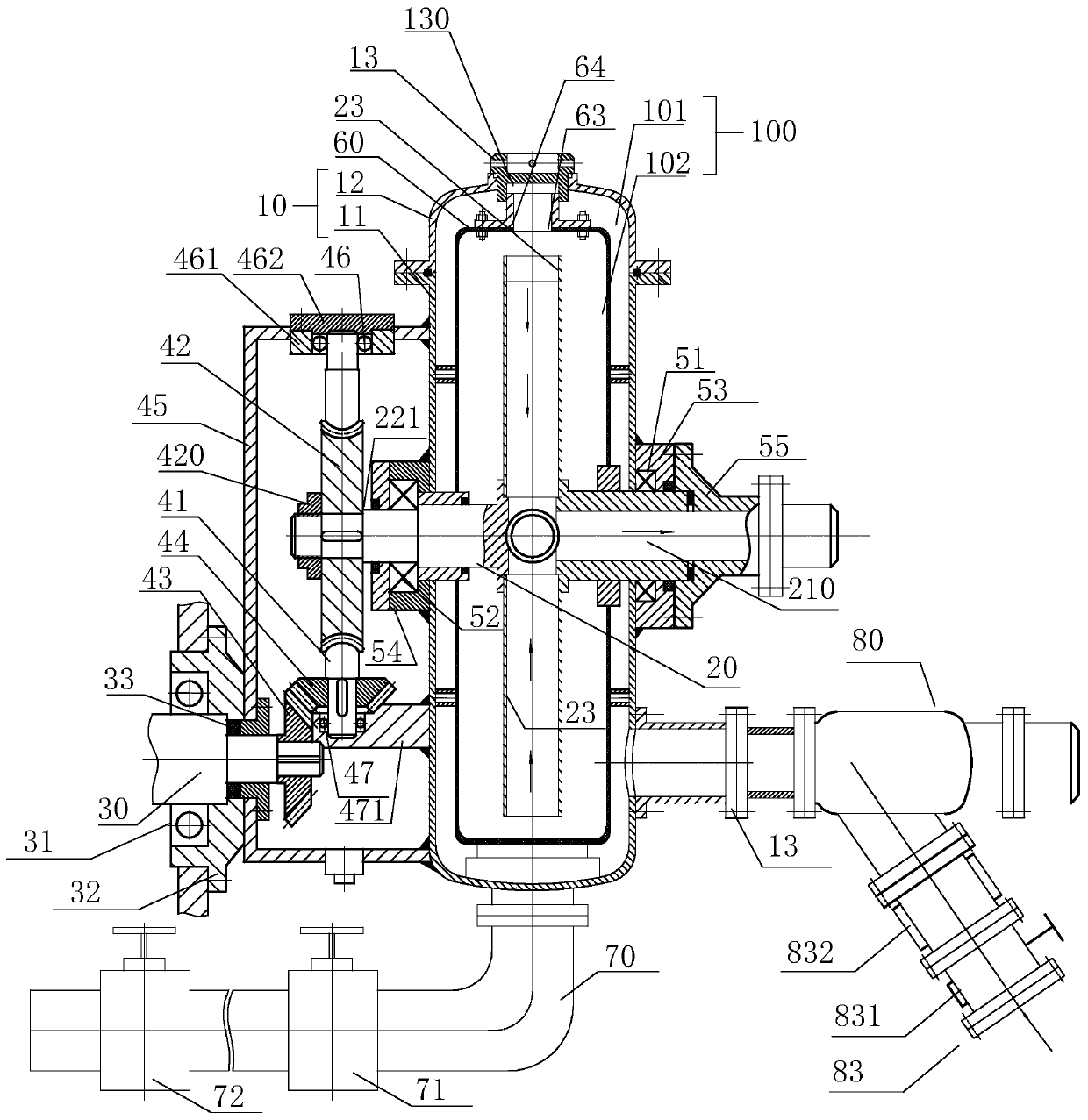
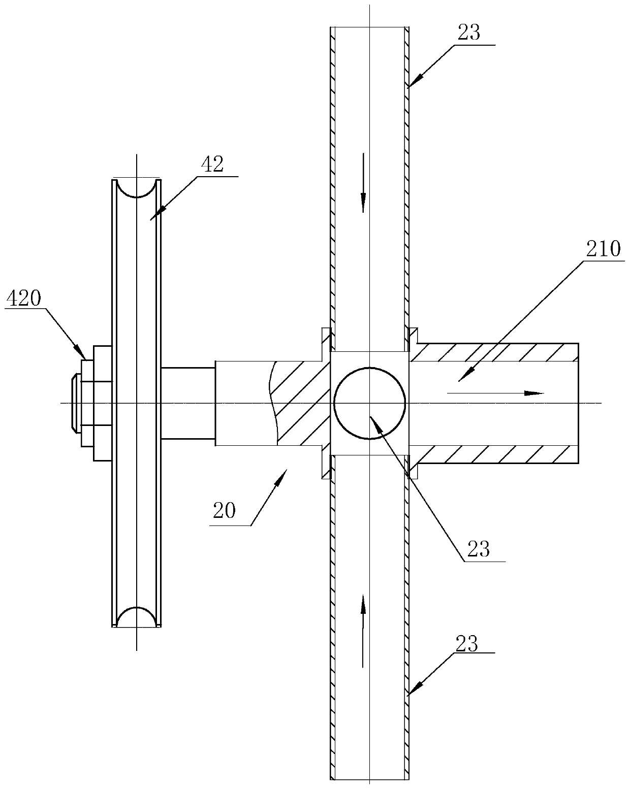
[0023] see Figure 1-Figure 6, a dynamic air intake liquid delivery device, including a housing 10 with a gas-liquid mixing chamber 100 and a gas-liquid delivery adjustment assembly arranged in the gas-liquid mixing chamber 100, the housing 10 is provided with a gas-liquid mixing chamber 100 connected to The gas-liquid inlet through which the gas-liquid transport is adjusted includes a rotating shaft 20 with an axially arranged gas-liquid transporting channel 210 inside. One end of the shaft 20 passes through the casing 10 to form a gas-liquid outlet for communicating with the liquid inlet chamber of the hydraulic end of the reciprocating pump, and the other end passes through the casing 10 to drive and connect with an external power device to drive the rotating shaft 20 rotation; the rotating shaft 20 is also provided with at least two openi...


PUM


Abstract

The invention relates to a dynamic intake gas-liquid conveying device comprising a gas-liquid conveying regulation component. The gas-liquid conveying regulation component comprises a rotating shaft which is internally provided with a gas-liquid conveying channel arranged axially, and the two ends of the rotating shaft penetrate through the front and rear side walls of a shell, and are arranged rotatably; after one end of the rotating shaft penetrates through the shell, gas-liquid outlets are formed; the other end of the rotating shaft penetrates through the shell, and is in driving connectionwith an external power unit so that the rotating shaft is driven to rotate; the rotating shaft is further provided with at least two openings at intervals circumferentially, and the two openings communicate with the gas-liquid conveying channel; the openings are provided with gas-liquid conveying pipes arranged radially; and the gas-liquid conveying pipes run through the gas-liquid outlets through the openings and the gas-liquid conveying channels, and gas phase media located at the upper area of a gas-liquid mixing chamber and liquid phase media located at the lower area of the gas-liquid mixing chamber can be sucked in the rotation process of the rotating shaft. The dynamic intake gas-liquid conveying device is not affected by gas-liquid specific gravity or gas-liquid position, and gas-liquid mixed conveying can be achieved effectively.

Description

technical field [0001] The invention relates to the technical field of fluid delivery, in particular to a dynamic intake fluid delivery device. Background technique [0002] In the process of fluid transportation in the industrial field, gas-liquid mixed pumps are often used to transport gas and liquid mixed fluids, such as crude oil and natural gas, liquid CO2 and CO2 gas, water and compressed air, nitrogen and water, shale In the transportation process of mixed fluids such as gas and water, especially in the process of oil production, the extracted crude oil often contains rich natural gas, that is, the medium to be transported in oil extraction includes both liquid medium-crude oil and gas-phase medium- natural gas. In the process of crude oil and natural gas transportation in oil fields, at present, separators and storage tanks are generally equipped on site, and gas-liquid is carried out by rotating centrifugal vortex pumps, screw pumps, rotor pumps or reciprocating pl...

Claims


Application Information

Patent Timeline
Patent Type & Authority Applications(China)
IPC IPC(8): F04B19/06F04B53/16F04B53/20
Inventor 陈明海陈英峰
Owner NINGBO HELI MECHANICAL PUMP CO LTD
Learn More