A differential pressure type rapid inflation valve special for plasma rupture protection

A plasma, differential pressure technology, applied in the direction of valve, valve device, functional valve type, etc. for inflation, which can solve problems such as damage, large escape current, strong mechanical stress, etc.

Active Publication Date: 2021-01-19
HEFEI INSTITUTES OF PHYSICAL SCIENCE - CHINESE ACAD OF SCI
View PDF4 Cites 0 Cited by
  • Summary
  • Abstract
  • Description
  • Claims
  • Application Information

AI Technical Summary

Problems solved by technology

[0002] In the tokamak discharge test, due to plasma control, magnetic fluid instability, impurities, high-energy escaping particles, etc., the rupture of the plasma is unavoidable
Especially in the main research content of realizing the steady-state operation of the tokamak fusion reactor—maintaining the discharge of the steady-state high-parameter plasma, the plasma rupture discharge will cause serious damage, such as the large thermal load of the first wall, the strong Mechanical stress, large escape current, etc., even cause serious damage to the deflector target plate, first wall parts and even the device

Method used


Image

  • A differential pressure type rapid inflation valve special for plasma rupture protection

Examples


Embodiment Construction

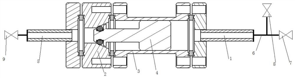
[0015] Such as figure 1 As shown, a differential pressure fast inflation valve dedicated to plasma rupture protection includes an inlet flange 1, a sealing cone 2, a high-pressure chamber 3, a valve core 4 and an air outlet flange 5, and the sealing cone 2 One end of the high pressure chamber 3 is sealed and fixedly connected, the other end of the high pressure chamber 3 is sealed and fixedly connected with the inlet flange 1, the other end of the sealing cone 2 is sealed and fixedly connected with the outlet flange 5, and the inlet flange 1. The high-pressure chamber 3, the sealing cone 2 and the air outlet flange 5 form a working chamber together. The valve core 4 is installed in the working chamber. One end of the valve core 4 is a conical structure, and the other end is a cylindrical structure. , a thin cylindrical rod is connected between the conical structure and the cylindrical structure, and a tapered groove matching the conical structure of the valve core 4 is opened ...


PUM


Abstract

The invention discloses a special differential pressure type rapid inflation valve for plasma disruption and protection. A sealing cone is fixedly connected to one end of a high-pressure cavity; the other end of the high-pressure cavity is fixedly connected with an air inlet flange in a sealing manner; the other end of the sealing cone is fixedly connected with an air outlet flange in the sealingmanner; the air inlet flange, the high-pressure cavity, the sealing cone and the air outlet flange form a working cavity together; a valve element is installed in the working cavity; and one end of the valve element is of a conical structure, and the other end of the valve element is of a cylindrical structure. According to the special differential pressure type rapid inflation valve for plasma disruption and protection, by adopting a pure mechanical differential pressure type opening manner, the valve is not influenced by electricity, magnetic fields and the like; and the structure of the valve element is designed to be of a structure with one conical end and the cylindrical end, the conical end plays a sealing effect through a sealing ring, and the cylindrical end is closely matched withthe interior of the high-pressure cavity in a cylinder of the high-pressure cavity, on one hand, the limiting effect is exerted, and on the other hand, the flow limiting effect is exerted.

Description

technical field [0001] The invention relates to the fields of vacuum technology, high-pressure technology and magnetic confinement fusion technology, in particular to a differential-pressure fast gas-filling valve dedicated to plasma rupture protection. Background technique [0002] In the tokamak discharge test, due to plasma control, magnetic fluid instability, impurities, high-energy escaping particles and other reasons, the rupture of the plasma is unavoidable. Especially in the main research content of realizing the steady-state operation of the tokamak fusion reactor—maintaining the discharge of the steady-state high-parameter plasma, the plasma rupture discharge will cause serious damage, such as the large thermal load of the first wall, the strong Mechanical stress, large escape current, etc., even cause serious damage to the target plate of the deflector, the first wall parts and even the device. Although the operating limits of different parameters of the existing...

Claims


Application Information

Patent Timeline
Patent Type & Authority Patents(China)
IPC IPC(8): F16K24/06
Inventor 庄会东张晓东胡建生陈鑫鑫
Owner HEFEI INSTITUTES OF PHYSICAL SCIENCE - CHINESE ACAD OF SCI
Why Eureka
Try Eureka