Multi-functional clothing display rack

A clothing display rack and multi-functional technology, applied in the field of display racks, can solve the problems of low selectivity, the inability to adjust the height of the display rack freely, and affect the customer's shopping experience, so as to achieve convenient shopping and high selectivity Effect

Active Publication Date: 2019-06-14
温州青苗影视传媒有限公司
View PDF7 Cites 12 Cited by
  • Summary
  • Abstract
  • Description
  • Claims
  • Application Information

AI Technical Summary

Problems solved by technology

However, the height of the display stand cannot be adjusted freely, which is not convenient for children to choose and buy. Moreover, when hanging long ski

Method used


Image

  • Multi-functional clothing display rack
  • Multi-functional clothing display rack
  • Multi-functional clothing display rack

Examples


specific Embodiment approach 1

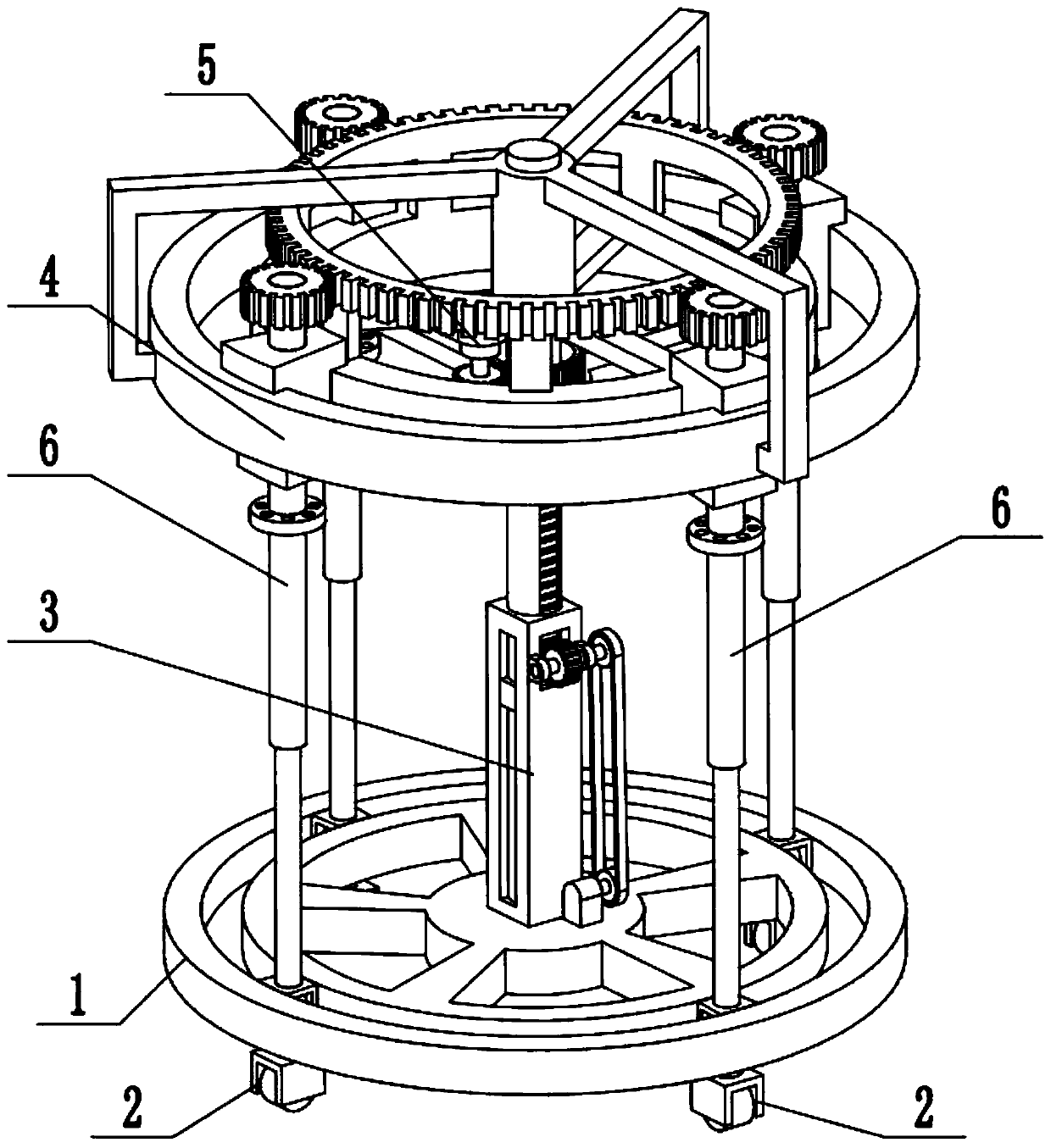
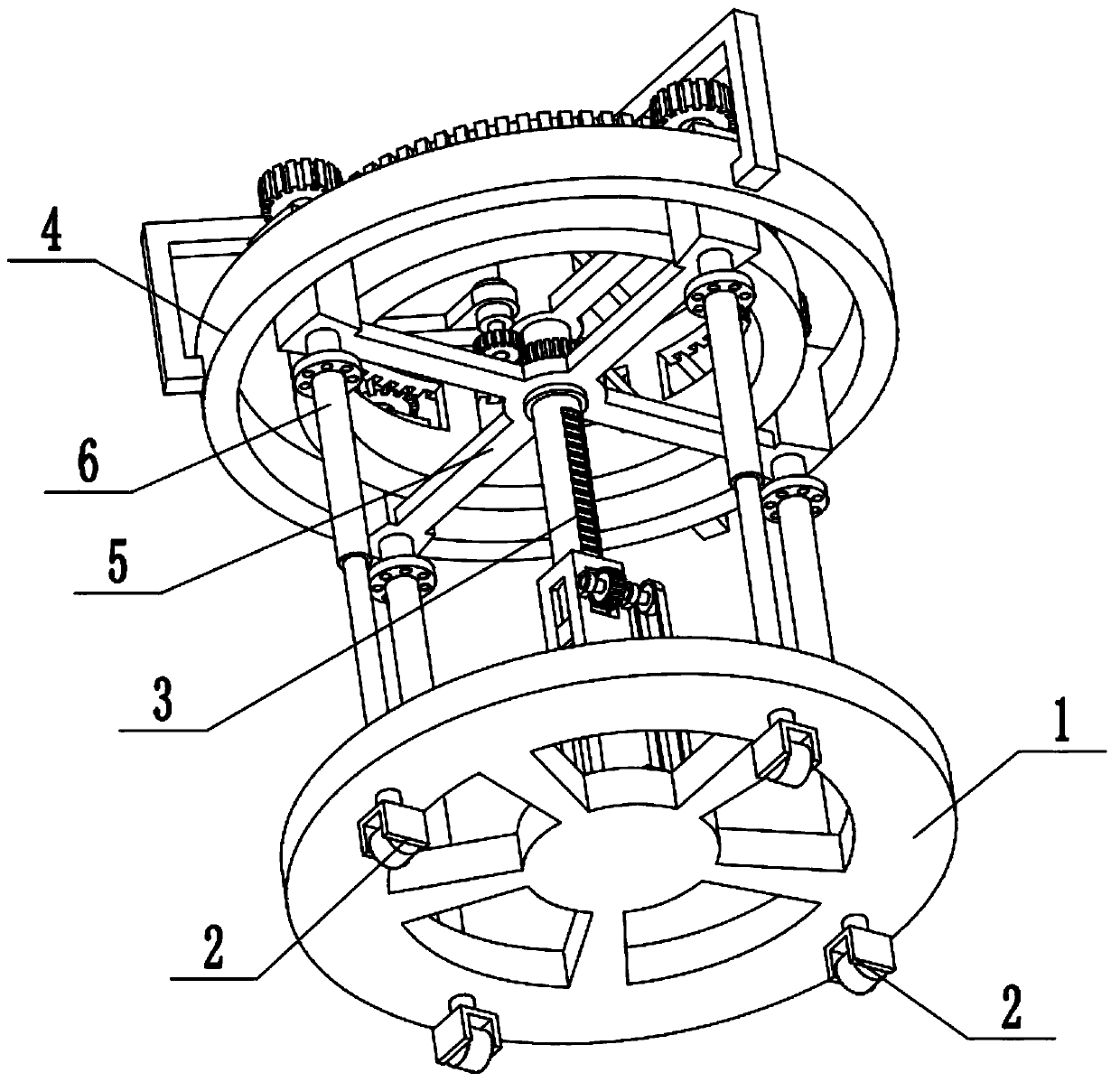
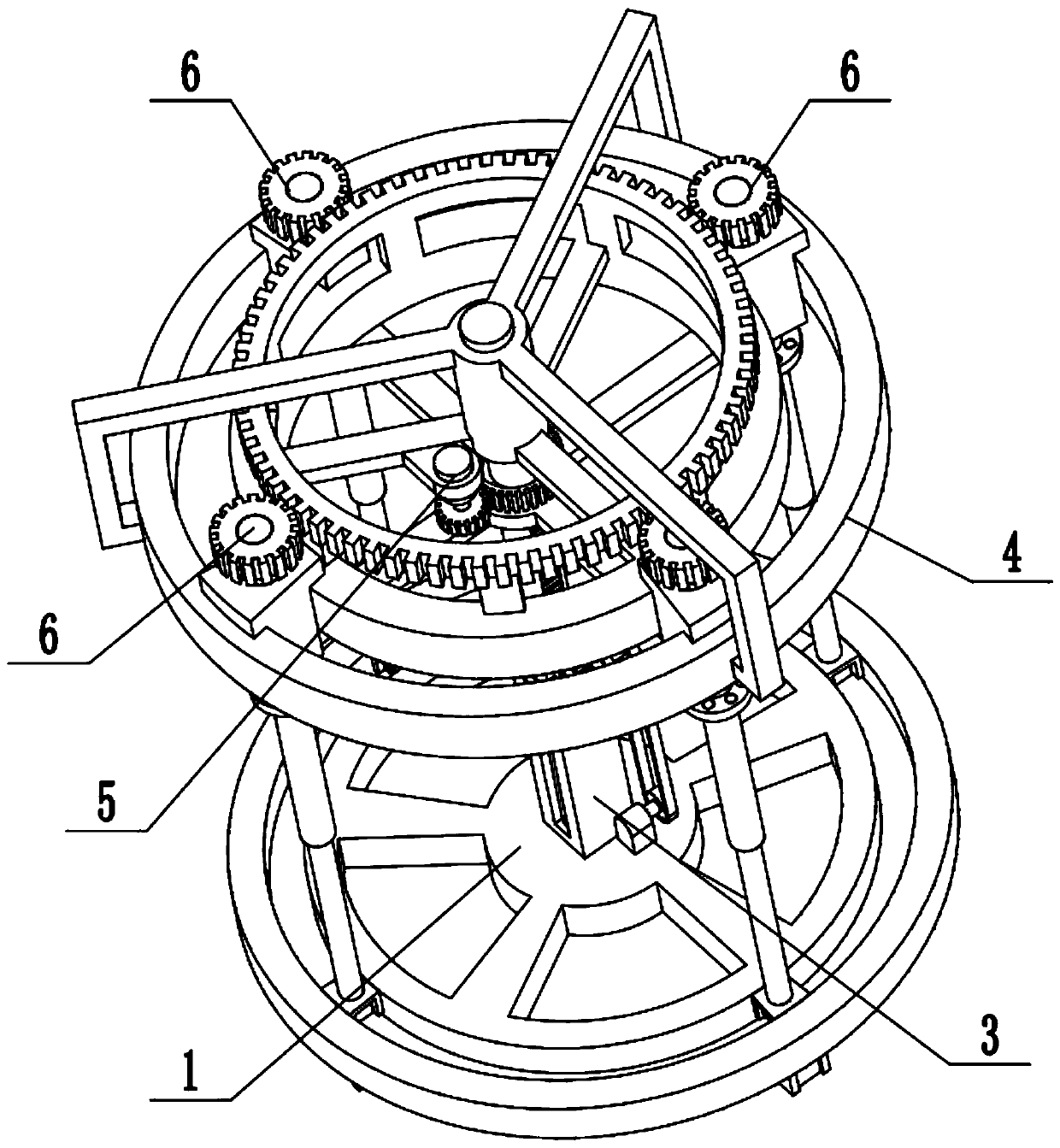
[0025] Combine below Figure 1-8 Describe this embodiment, a multifunctional clothing display rack, including a base 1, universal wheels 2, a height adjustment assembly 3, an upper slide assembly 4, a rotation drive assembly 5 and a rotation display rack 6, the height adjustment assembly 3 The lower end of the base is fixedly connected to the base 1, the upper slide assembly 4 is fixedly connected to the upper end of the base 1, the rotation drive assembly 5 is fixedly connected to the upper slide assembly 4, the rotation drive assembly 5 is rotatably connected to the height adjustment assembly 3, and the rotation There are four display racks 6, and the four rotating display racks 6 are evenly arranged on the upper slide assembly 4. The upper ends of the four rotating display racks 6 are all engaged with the upper slide assembly 4. The lower ends of both are slide-fitted and connected to the base 1. When the present invention is in use, after the height adjustment assembly 3 ...

specific Embodiment approach 2

[0026] Combine below Figure 1-8 To illustrate this embodiment, the base 1 is provided with an annular sliding groove 1-1.

specific Embodiment approach 3

[0027] Combine below Figure 1-8To illustrate this embodiment, the height adjustment assembly 3 includes a rectangular support base 3-1, a telescopic rod 3-2, a limit ring 3-3, a rack 3-4, a limit block 3-5, and a side slide groove 3 -6, rectangular slot 3-7, height adjustment gear 3-8, gear rotating shaft 3-9, shaft support plate 3-10, driven pulley 3-11, driving pulley 3-12 and height adjustment motor 3- 13. The rectangular support seat 3-1 is fixedly connected to the center of the base 1, the lower end of the telescopic rod 3-2 is slidingly fitted and connected in the rectangular support seat 3-1, and the middle end of the telescopic rod 3-2 is fixedly connected to the limit position of the connecting rod The ring 3-3 and the lower end of the telescopic rod 3-2 are provided with rack placement grooves, the rack 3-4 is fixedly connected in the rack placement groove, and the left and right sides of the lower end of the telescopic rod 3-2 are respectively fixedly connected wit...


PUM


Abstract

The invention relates to a display rack, in particular to a multi-functional clothing display rack. The multi-functional clothing display rack comprises a base, universal wheels, a height adjusting assembly, an upper sliding base assembly, a rotary driving assembly and four rotary display rack bodies. The multi-functional clothing display rack has the advantages that the display rack can be rotated, multiple sets of clothing can be displayed many angles, display is comprehensive, a customer can comprehensively view multiple sets of clothing hung around the display rack, and it is convenient for the customer to select and purchase the clothing; the height can be freely adjusted, various clothing types can be displayed, and the selectivity is high. The lower end of the height adjusting assembly is fixedly connected to the base, the upper sliding base assembly is fixedly connected to the upper end of the base, the rotary driving assembly is fixedly connected to the upper sliding base assembly, the rotary driving assembly is rotationally connected to the height adjusting assembly, the four rotary display rack bodies are uniformly arranged around the upper sliding base assembly, the upper ends of the four rotary display rack bodies are in meshing and transmission connection with the upper sliding base assembly, and the lower ends of the four rotary display rack bodies are in cooperative sliding connection with the base.

Description

technical field [0001] The invention relates to a display rack, more specifically a multifunctional clothing display rack. Background technique [0002] The existing patent number is CN201620792636.9 for an electric clothing display stand. This utility model discloses an electric clothing display stand, which consists of a lower hanger tube a, an upper hanger tube a, a wireless induction probe, a hanger rod, a wireless induction Signal receiver, base, upper hanger tube d, upper hanger tube b, upper hanger tube c, interval point, lower hanger tube b, switch, upper bearing sleeve, reduction gear, motor, reducer, lower bearing sleeve , transmission gear, single-chip microcomputer, external power line, and hanger body; the wireless induction probe is used to sense whether there are customers standing in front of the display stand, and the induction signal received by the wireless induction signal receiver is connected to the single-chip microcomputer to drive the motor to rotate...

Claims


Application Information

Patent Timeline
IPC IPC(8): A47F7/19A47F5/02A47F5/10
Inventor 刘士超
Owner 温州青苗影视传媒有限公司
Why Eureka
Try Eureka