Movable vertical waste compression transfer station

A garbage compression and mobile technology, which is applied in the direction of garbage transmission, garbage collection, loading/unloading, etc., can solve the problems of unfavorable promotion and application, long transfer period, and increased garbage transfer costs, so as to avoid environmental pollution and increase the amount of garbage storage , Improve the effect of garbage disposal capacity

Inactive Publication Date: 2019-06-18
四川绿冶科技有限责任公司
View PDF0 Cites 0 Cited by
  • Summary
  • Abstract
  • Description
  • Claims
  • Application Information

AI Technical Summary

Problems solved by technology

Due to design defects, the existing garbage compression transfer station has poor compression capacity, long transfer period, secondary rancidity of garbage during the transfer process, and a large amount of odorous gas, which is not conducive to the development of sanitation cities. The entire transfer technology is relatively Rough, a large amount of garbage and sewage generated cannot be treated in time. In the high temperature environment, the secondary rancidity and secondary pollution of the garbage stored in the transfer station are accelerated. At the same time, the poor matching between the transfer station and the garbage transfer vehicle makes the transfer difficult. Large, increasing the cost of garbage transfer, which is not conducive to popularization and application

Method used


Image

  • Movable vertical waste compression transfer station

Examples


Embodiment Construction

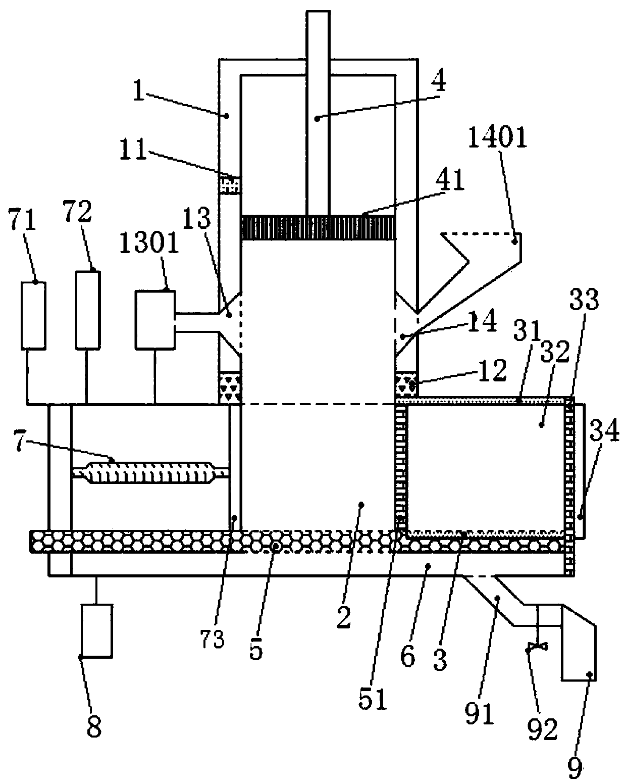
[0028] Such as figure 1 As shown, a mobile vertical garbage compression transfer station is characterized in that the structure includes a frame (1), a compression chamber (2) arranged inside the frame (1), and a storage chamber is arranged on the right side of the compression chamber (2) (3), the main compression oil cylinder (4) is arranged directly above the compression chamber (2), and the inside of the main compression oil cylinder (4) is provided with a stainless steel pressure head (41) that can slide up and down along the inner wall of the main compression oil cylinder (4). The caliber of the head (41) matches the caliber of the inner wall of the compression chamber (2); the left side of the compression chamber (2) is a horizontal push device (7), and the right end of the horizontal push device (7) is provided with a horizontal push head (73), and the horizontal The push head (73) is positioned on the left edge of the compression chamber (2);

[0029] The compression ...


PUM


Abstract

The invention relates to a movable vertical waste compression transfer station. The movable vertical waste compression transfer station comprises a frame and a compression chamber arranged on the inner side of the frame. A storage chamber is arranged on the right side of the compression chamber. A main compression oil cylinder is arranged over the compression chamber. A stainless steel pressing head capable of sliding up and down along an inner wall of the main compression oil cylinder is arranged in the main compression oil cylinder. The caliber of the stainless steel pressing head is matchedwith the caliber of the inner wall of the compression chamber. A horizontal pushing device is arranged on the left side of the compression chamber. A horizontal pushing and pressing head is arrangedat the right end of the horizontal pushing device and is positioned at the left edge of the compression chamber. A rigid supporting plate is additionally arranged at the bottom of the compression chamber. Uniformly-arranged filtering micropores are machined in the rigid supporting plate. A sewage collecting tank is arranged at the bottom of the rigid supporting plate. The bottom of the sewage collecting tank communicates with a waste liquid collecting tank through a flow guide pipe. The operation efficiency of the waste transfer station is improved, secondary rancidity decay and secondary pollution of waste in the transfer station are reduced, and construction requirements of environment-friendly cities are met.

Description

technical field [0001] The invention relates to the technical field of environmental protection equipment, in particular to a mobile vertical garbage compression transfer station. Background technique [0002] As a special equipment for waste transfer treatment in the process of sanitation construction, the garbage compression transfer station plays an important role in promoting the construction of a modern intelligent sanitation city and the development of urbanization, which is related to the comfort of urban residents and the appearance of the city. Due to design defects, the existing garbage compression transfer station has poor compression capacity, long transfer period, secondary rancidity of garbage during the transfer process, and a large amount of odorous gas, which is not conducive to the development of sanitation cities. The entire transfer technology is comparatively poor. Rough, the large amount of garbage and sewage produced cannot be treated in time. In the h...

Claims


Application Information

Patent Timeline
IPC IPC(8): B65F9/00
Inventor 郭显富
Owner 四川绿冶科技有限责任公司
Why Eureka
Try Eureka