Electric valve stator and electric valve

A technology of electric valves and stators, which is applied in the direction of valve devices, valve details, engine components, etc., and can solve problems such as the position deviation of the stator 91

Active Publication Date: 2020-09-01
SAGINOMIYA SEISAKUSHO INC
View PDF7 Cites 0 Cited by
  • Summary
  • Abstract
  • Description
  • Claims
  • Application Information

AI Technical Summary

Problems solved by technology

Therefore, for example if Figure 8 As shown, when the weight of the stator 91 is increased in the axis X direction of the valve device main body 92, the bracket 93 is easily deflected in the axis X direction as shown by the two-dot chain line in the figure, and the stator 91 is easily damaged due to excessive vibration or the like. 91 moves in the axis X direction relative to the valve device main body 92, so there is a problem that the position of the stator 91 tends to shift.

Method used


Image

  • Electric valve stator and electric valve
  • Electric valve stator and electric valve
  • Electric valve stator and electric valve

Examples


Embodiment Construction

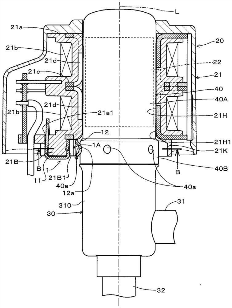
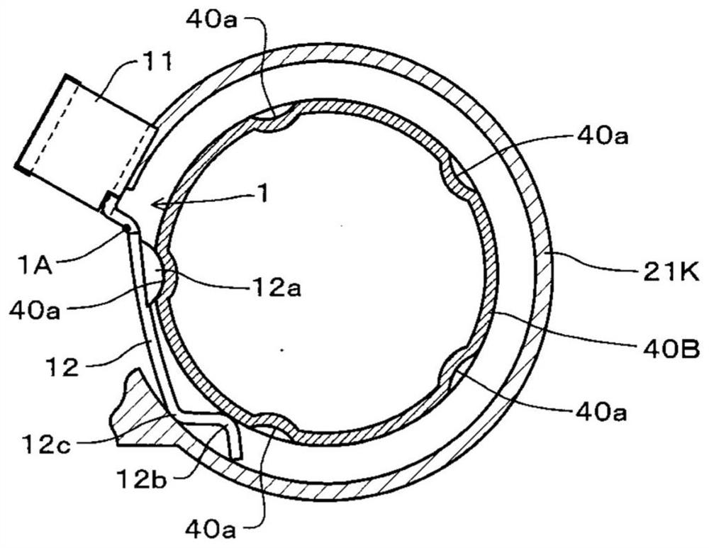
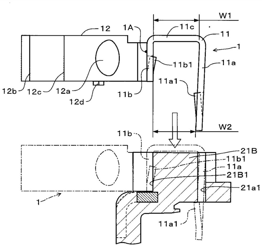
[0028] Next, embodiments of the motor-driven valve stator and the motor-driven valve according to the present invention will be described with reference to the drawings. figure 1 is a partially cutaway side view of an electric valve according to an embodiment, figure 2 Yes figure 1 A cross-sectional view in the direction of the B-B arrow, image 3 is a diagram showing the bracket and the fixing block of the first embodiment, Figure 4 It is a longitudinal sectional view and a bottom view of the electric valve stator of the first embodiment, Figure 4 (A) is Figure 4 (B) A-A sectional view. In addition, the concept of "up and down" in the following explanations is the same as figure 1 The upper and lower correspondences in the attached drawings.

[0029] like figure 1 as well as Figure 4 As shown, the electric valve has a bracket 1 as an "elastic member", a stepping motor 20 as a "motor part", a valve main body 30, and a cylindrical-shaped "cylindrical part" made...


PUM


Abstract

The invention provides a stator for an electric valve and an electric valve. In an electric valve in which a stator constituting a motor part is attached to a valve device in which a case part (40) accommodating a magnetic rotor (22) is assembled to a valve body (30), the number of steps for fixing the stator (21) to the case part ( 40) deflection of the bracket (1) in the direction of the axis L to securely mount the stator (21) to the housing. The bracket (1) is attached around the opening (21H1) of the stator (21) on the valve main body (30) side. The bracket (1) is composed of a base (11) and an elastic piece (12). The convex part (12a) of the elastic piece (12) is engaged with the concave part (40a) of the shell part. The elastic piece (12) is formed such that the bent portion (1A) of the elastic piece (12) on the base portion (11) side is parallel to the axis L.

Description

technical field [0001] The present invention relates to a stator for an electric valve used in a refrigeration cycle system such as an air conditioner, and an electric valve provided with the stator for an electric valve. Background technique [0002] Conventionally, as such an electric valve, there is an electric valve that operates a valve member in a valve main body by utilizing the rotation of a magnetic rotor of a motor unit such as a stepping motor. In such an electric valve, it is necessary to close the flow path of the fluid, and the magnetic rotor of the motor unit is accommodated in a cylindrical case part forming a closed structure together with the valve body. Furthermore, the stator of the motor part has a structure arrange|positioned at the outer periphery of a case part. For example, JP-A-2006-20479 (Patent Document 1) and JP-A-2017-15104 (Patent Document 2) disclose the same electric valve. [0003] prior art literature [0004] Patent Document 1: Japanese...

Claims


Application Information

Patent Timeline
Patent Type & Authority Patents(China)
IPC IPC(8): F16K31/04F25B41/06F25B41/35
Inventor 土井琢郎中川大树
Owner SAGINOMIYA SEISAKUSHO INC
Why Eureka
Try Eureka