Backrest device

A backrest and backrest technology, applied in transportation and packaging, special positions of vehicles, chairs, etc., can solve problems such as the weakening of the sliding plate and ratchet meshing state

Inactive Publication Date: 2003-08-13
ARACO CORP
View PDF1 Cites 0 Cited by
  • Summary
  • Abstract
  • Description
  • Claims
  • Application Information

AI Technical Summary

Problems solved by technology

For this reason, when there is a load on the backrest device in this state, the sliding plate has a slight rotation due to the looseness between the connecting parts and the sliding plate, and the meshing state of the sliding plate and the ratchet is weakened. status

Method used


Image

  • Backrest device
  • Backrest device
  • Backrest device

Examples


Embodiment Construction

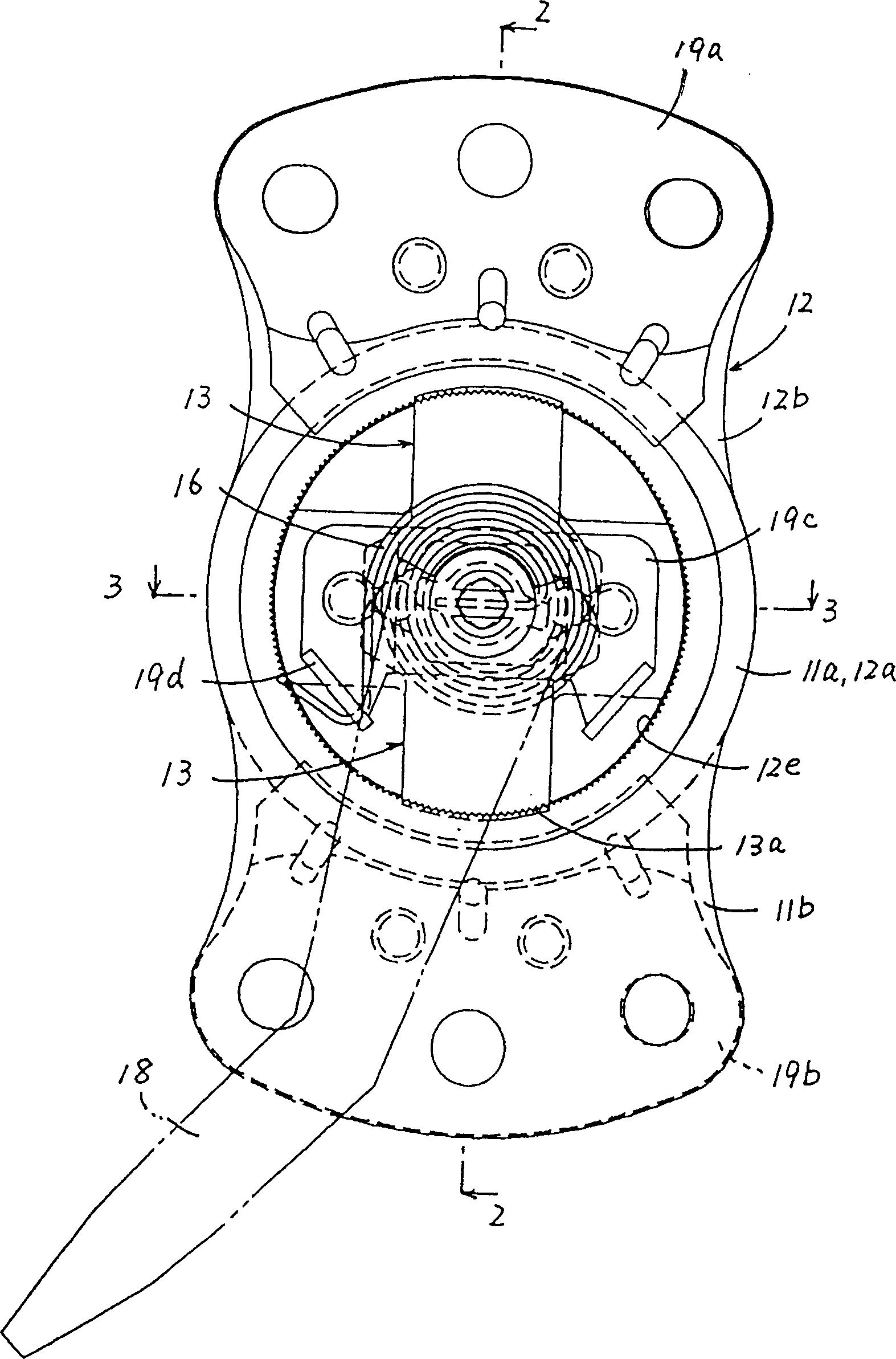
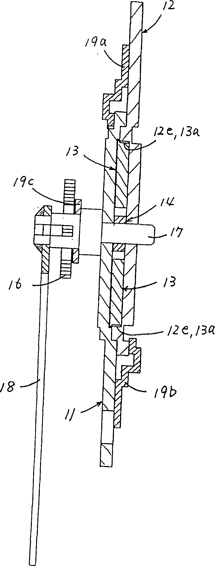
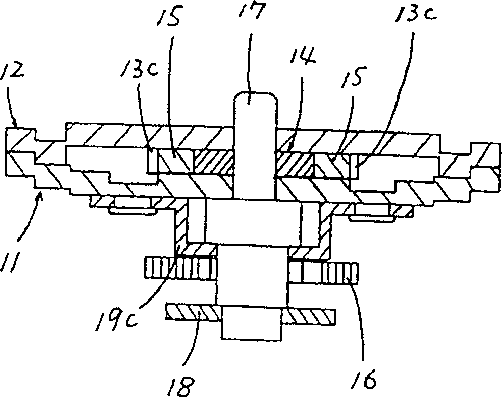
[0028] Embodiments of the present invention are described below with reference to the drawings. Figure 1 ~ Figure 3 It shows the first example of the backrest device according to the present invention. The backrest device is composed of a first connecting arm 11 , a second connecting arm 12 , a pair of sliding plates 13 , an operating cam 14 , a pair of rollers 15 , a coil spring 16 , a hinge shaft 17 and an operating rod 18 .

[0029] The first connecting arm 11 and the second connecting arm 12 accommodate two sliding plates 13, the action cam 14 and the two rollers 15 in a state overlapping with each other, and are in a supported state rotatably around the hinge shaft 17. The first connecting arm 11 is fixed on the side rear of the chair seat side not shown among the figure, and the 2nd connecting arm is fixed on the side below of the chair back side not drawn among the figure.

[0030] In this way, the backrest device connects the back of the chair to the rear end of the ...


PUM


Abstract

An arc shape bore part on the back part of a slide pole is borne by an arc shape bearing part of a bearing plate to keep an engaging condition between the slide pole and a ratchet to regulate the rotation of the slide pole under load action to prevent lowering of engaging strength caused by the rotation of the slide pole to increase the engaging strength. It prevents lowering of the interlocking strength between a slide pole and a ratchet under a load action in a reclining device in which a slide pole assembled with a first connecting arm is slid to engage with a ratchet equipped on a second connecting arm to lock both arms.

Description

technical field [0001] The invention relates to a backrest device Background technique [0002] As a form of the backrest device, there is a backrest device that includes a pair of connecting arms installed on the seat side of the chair and the back side of the chair respectively, a hinge shaft that supports the two connecting arms and can rotate relative to the center of the support axis, and can A sliding plate that is slidably installed on one of the two connecting arms and can be engaged with a ratchet provided on the other connecting arm allows the sliding plate to slide and selectively forms the engagement state and non-engaging state of the sliding plate to the ratchet. Engaged state action cam. [0003] In the backrest device of the above-mentioned form, the relative rotation of the two connecting arms is limited by forming the above-mentioned meshing state, so that the back of the chair is locked relative to the chair seat, and the relative rotation of the two conn...

Claims


Application Information

Patent Timeline
Patent Type & Authority Patents(China)
IPC IPC(8): B60N2/10A47C1/025B60N2/235
CPCB60N2/2356B60N2/236
Inventor 浅野诚
Owner ARACO CORP
Why Eureka
Try Eureka