Heat exchanger for washing ship exhaust gas
A waste gas washing and heat exchanger technology, which is applied to heat exchange equipment, heat exchanger types, heat exchanger shells, etc., can solve the problems of temperature adjustment lag and the inability to quickly adjust the temperature of materials, etc., and achieve the effect of reducing the delay effect
- Summary
- Abstract
- Description
- Claims
- Application Information
AI Technical Summary
Problems solved by technology
Method used
Image

Examples
Embodiment 1
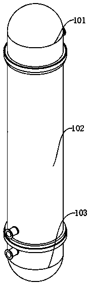
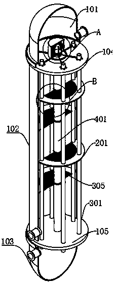
[0028] A heat exchanger for scrubbing exhaust gas from ships, including: an upper cooling liquid shell 101, a heat exchange shell 102 and a lower cooling liquid shell 103, and also includes: an upper cooling tube fixing plate 104 and a lower cooling tube fixing plate 105, the upper cooling The lower end of the liquid shell 101 is fixedly connected to the upper surface of the upper cooling tube fixing plate 104, the lower surface of the upper cooling tube fixing plate 104 is fixedly connected to the upper end of the heat exchange shell 102, and the lower end of the heat exchange shell 102 is fixedly connected to the upper surface of the lower cooling tube fixing plate 105. The lower surface of the lower cooling tube fixing plate 105 is fixedly connected to the upper end of the lower cooling liquid shell 103, and multiple sets of baffle plates are uniformly fixed and installed inside the heat exchange shell 102, and the edges of the upper cooling tube fixing plate 104 and the lowe...
Embodiment 2
[0033] Embodiment 2: the difference based on Embodiment 1 is;
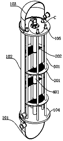
[0034] The heat exchange self-regulating tube includes: a temperature-sensing moving tube 401, an upper heat-insulating shell 402, a lower temperature-sensing shell 403, an anti-shock sleeve 404 and a pneumatic pipeline 405, and an upper heat-insulating shell 402 is fixedly installed on the upper surface of the upper cooling tube fixing plate 104, The upper end of the temperature-sensing moving tube 401 is movably socketed inside the upper thermal insulation shell 402, and the lower temperature-sensing shell 403 is fixedly installed on the axis of the lower surface of the lower cooling tube fixed plate 105, and the temperature-sensing moving tube 401 is movably socketed inside the lower temperature-sensing shell 403 At the lower end, multiple groups of pneumatic pipes 405 are fixedly installed in the inner wall of the upper heat preservation shell 402. The inlet of the pneumatic pipe 405 is arranged inside the uppe...
Embodiment 3
[0037] Embodiment 3: the difference based on embodiment 1 and 2 is;
[0038] The baffle includes: a baffle fixed ring 201, a drainage plate 202, a drainage groove 203 and a drainage connection ring 204, the baffle fixed ring 201 is fixedly connected to the heat exchange shell 102, and the inner side of the baffle fixed ring 201 is fixedly connected to the drainage connection ring 204 A drainage plate 202 is fixedly mounted on the inner side of the drainage connection ring 204 , and drainage grooves 203 are provided on both sides of the drainage plate 202 .
[0039] The present invention is equipped with a baffle, and when in use, the temperature-sensing moving tube 401 can react in real time to the heat-exchanging material inside the heat-exchanging shell 102, thereby driving the temperature-sensing moving tube 401 to move back and forth, and driving the drainage plate 202 moves back and forth, so as to change the movement of the heat exchange material, and the drainage groove...
PUM
 Abstract
Description
Claims
Application Information
 - Generate Ideas
- Intellectual Property
- Life Sciences
- Materials
- Tech Scout
- Unparalleled Data Quality
- Higher Quality Content
- 60% Fewer Hallucinations
Browse by: Latest US Patents, China's latest patents, Technical Efficacy Thesaurus, Application Domain, Technology Topic, Popular Technical Reports.
© 2025 PatSnap. All rights reserved.Legal|Privacy policy|Modern Slavery Act Transparency Statement|Sitemap|About US| Contact US: help@patsnap.com