Split type buffering mechanism used for coupler buffers

A buffer mechanism and split-type technology, applied in buffers, railway car body parts, transportation and packaging, etc., can solve the problems of large wheel set lateral force, excessive structure, truck derailment, etc., to reduce wheel set lateral force, High positional stability, the effect of avoiding derailment of trucks

Inactive Publication Date: 2019-06-25
株洲飞马橡胶实业有限公司
View PDF9 Cites 0 Cited by
  • Summary
  • Abstract
  • Description
  • Claims
  • Application Information

AI Technical Summary

Problems solved by technology

The existing coupler buffer is divided into a group of N buffer elements, which are responsible for the compression when the vehicle starts and the compression when the vehicle decelerates. This kind of coupler buffer is not only complicated in structure, but also has a long and heavy structure, which is troublesome and time-consuming to repair and replace. Long, resulting in low installation and maintenance efficiency
[0003] In addition, for the current port truck track and other workplaces where the radius of the curved line is very small (about R50m) and there are many curves, the existing coupler buffer device structure is too long and too heavy, and the existing coupler buffer element structure cannot meet the requirements. The driving requirements with a small curve radius are likely to generate a large wheel set lateral force, resulting in derailment and rollover accidents of the truck

Method used


Image

  • Split type buffering mechanism used for coupler buffers
  • Split type buffering mechanism used for coupler buffers
  • Split type buffering mechanism used for coupler buffers

Examples


Embodiment 1

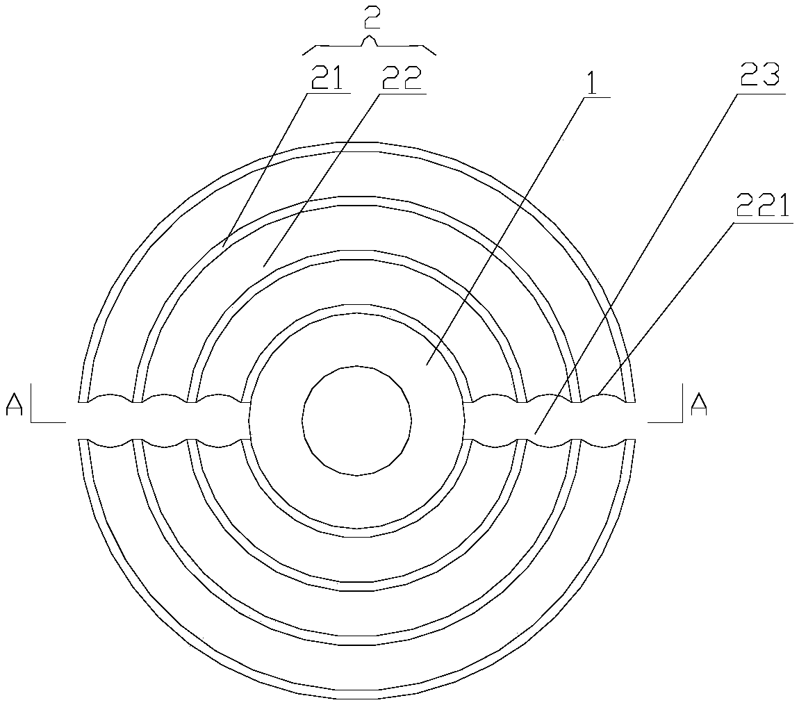
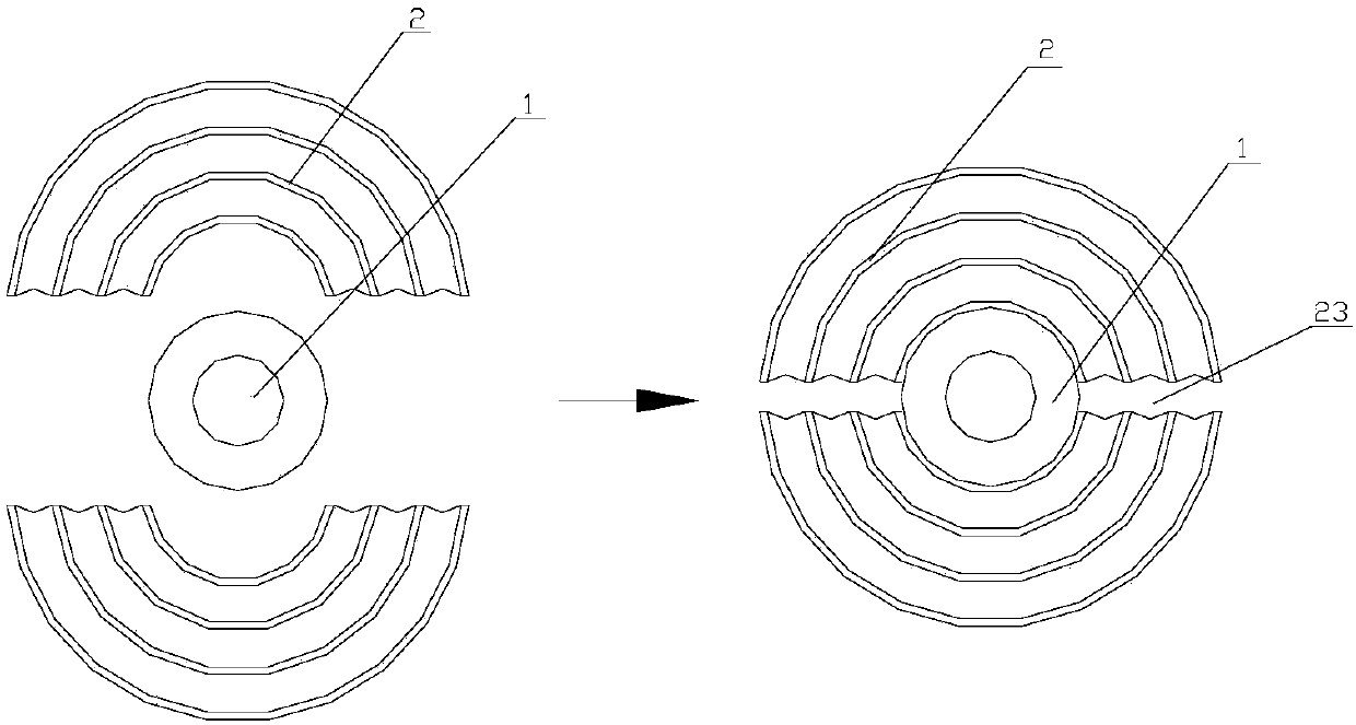
[0029] Such as Figure 1 to Figure 3 As shown, the split-type buffer mechanism for the coupler buffer of this embodiment includes an inner core 1 in the middle and two buffer units 2 arranged symmetrically along the inner core 1. On the other hand, the inner core 1 is a ring structure, and the buffer unit 2 is composed of several arc-shaped metal partitions 21 and several arc-shaped elastic bodies 22 arranged in a cross arrangement.

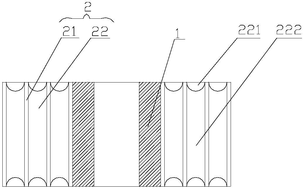
[0030] In this embodiment, the thickness of the elastic body 22 is not less than twice the thickness of the metal separator 21 .

[0031] In this embodiment, the elastic body 22 is a rubber structure, and the elastic body 22 is fixedly connected with the metal separator 21 by vulcanization bonding.

[0032] In this embodiment, there are three metal separators 21 and three elastic bodies 22 .

[0033] In this embodiment, both ends of the elastic body 22 are provided with arc-shaped grooves A221 , and the width of the arc-shaped grooves A221 is e...

Embodiment 2

[0038] Such as image 3 As shown, the difference between this embodiment and the first embodiment is that: the metal partition 21 and the elastic body 22 are connected in a horizontal stacking manner, and the outermost metal partition 21 is provided with a metal jacket for fastening 3, all the other are with embodiment 1.

[0039] The working principle of the above-mentioned embodiment is: when the vehicle is in a stopped state, the buffer structure 2 is in a free state, and the surroundings of the inner core 1 are not compressed; The elastic body 212 on the right side is in a compressed state, and the elastic body 212 on the left side of the inner core 1 is in a free state; when the vehicle is in a braking deceleration state, the buffer structure 2 is compressed to the left, and the elastic body 212 on the left side of the inner core 1 is in a compressed state , the elastic body 212 on the right side of the inner core 1 is in a free state, and the elastic body 212 on the lef...


PUM


Abstract

The invention discloses a split type buffering mechanism used for coupler buffers. The buffering mechanism includes a middle inner core and two buffering units symmetrically arranged along the inner core; the two buffering units are spliced on the two sides of the inner core by adopting a split type, and are not in contact with each other; the inner core is a circular ring structure, and the middle circular ring structure can be taken as an installation hole for connecting the buffering mechanism and a vehicle coupler; and the buffering units consist of multiple arc-shaped metal separating plate and multiple elastomers with arc-shaped structures through cross arrangement. The buffering mechanism is simple in structure, convenient in installation and maintenance and high in installation andmaintenance efficiency on the basis of guaranteeing a certain compression stroke, maximum acting force, buffering capacity and energy absorption rates, so that lightweight development of whole coupler buffers can be realized; and the buffering mechanism can effectively reduce wheelset transverse force, so that accidents of the derailment and rollover of trucks can be avoided, and therefore, highoperation safety can be achieved.

Description

technical field [0001] The invention relates to a buffer mechanism, in particular to a split type buffer mechanism used on a coupler buffer. Background technique [0002] The coupler is one of the important devices on the rail vehicle. Its main function is to connect the front and the car or the car and the car to ease the change of the traction force during the operation of the train or when starting, braking and shunting. Longitudinal impact and vibration caused by mutual collision of vehicles, and wheel set lateral force when vehicles turn, so as to reduce the damage to the structure of the vehicle body and improve the stability and comfort of train operation. The existing coupler buffer is divided into a group of N buffer elements, which are responsible for the compression when the vehicle starts and the compression when the vehicle decelerates. This kind of coupler buffer is not only complicated in structure, but also has a long and heavy structure, which is troublesome...

Claims


Application Information

Patent Timeline
Patent Type & Authority Applications(China)
IPC IPC(8): B61G11/00B61G11/18
Inventor 熊雪辉王春龙张永斌
Owner 株洲飞马橡胶实业有限公司
Why Eureka
Try Eureka